Download
1 / 48
480 likes | 609 Views
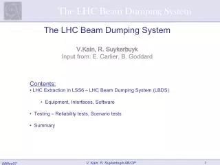
Beam Dumping system, operational experience and validation. B.Goddard On behalf of the LHC Beam Dump System teams The major contributions from J.Uythoven, E.Carlier, C.Bracco, W.Bartmann, L.Ducimeti è re, V.Senaj, V.Mertens and many others are warmly acknowledged . Overview.

E N D
Beam Dumping system, operational experience and validation B.Goddard On behalf of the LHC Beam Dump System teams The major contributions from J.Uythoven, E.Carlier, C.Bracco, W.Bartmann, L.Ducimetière, V.Senaj, V.Mertens and many others are warmly acknowledged
Overview Introduction to dump system Operational experience Reviews and audits Outstanding concerns B.Goddard LHC Machine Protection review 7/9/10
LHC beam dump overview (and acronyms) Dump block Dilution kickers Passive diluter Extraction septum Passive diluter Extraction kicker
Main subsystems and acronyms • Extraction kickers MKD • Extraction septa MSD • Dilution kickers MKB • Dump block TDE • Vacuum lines TD • Beam instrumentation BPM, BLM, BTV, BCT • Triggering and synchronisation unit TSU • Beam energy tracking system BETS • Slow control and supervision • Post operational checks IPOC, XPOC • Protection devices TCDS, TCDQ, TCSG
Extraction kickers MKD • Function: deflect beam into extraction septum during abort gap • Rise time of 3.0 ms, pulse length of 90 ms (1 full LHC turn) • Fixed deflection angle of 0.28 mrad (for 450 GeV to 7 TeV: 2 to 30 kV) • Main components • Kicker magnets (15 per beam) • Out of vacuum, strip-wound Fe cores, ceramic chambers, 18 kA single-turn coils • Generators (1 per magnet) • Capacitor discharge through 2 x 30 kV FHCT solid state switches • Transmission lines (8 parallel cables per magnet) 7.5 % Ceramic vacuum Chamber (coated) Conductor Strip-wound Core 90 ms MKD measured current waveforms (time in ms)
Extraction septa MSD • Function: deflect extracted beam vertically above the LHC • Fixed deflection angle of 2.4 mrad (for 450 GeV to 7 TeV) • Should have no influence on circulating beam • Main components • Warm “Lambertson” septum magnets (15 per beam, 5 each of 3 types) • Classical multi-turn design with 32-48 turns, 880 A current, water cooled • Baked vacuum chambers • Power convertor (1 per beam for 15 magnets in series) • 600 V Thyristor power convertor 32 - 48 turn Magnet coil Extracted beam Vacuum chamber Circulating beam Vacuum chamber Laminated Fe yoke
Dilution kickers MKB • Function: sweep beam in Lissajous figure on dump block • Separate horizontal and vertical systems • Sine and Cosine-like current shapes over 90 ms (1 full LHC turn) • Peak deflection angle of 0.28 mrad (450 GeV to 7 TeV) • Main components • Kicker magnets (4 H and 6 V per beam) • In vacuum, otherwise same technology as MKD • Generators (1 per magnet) • Single 30 kV FHCT solid state switch (resonant circuit for MKBH to dephase waveform) • Transmission lines (10 parallel cables per magnet)
Beam dump blocks TDE • Function: safely absorb the full LHC beam energy • Main components • Beam dump core TDE • 7.7 m long, 0.7 m graphite core, with graded density of 1.1/1.7 g/cm3 • 12 mm wall, stainless-steel welded pressure vessel, at 1.2 bar of N2 • ~1000 tonnes of concrete/steel radiation shielding blocks 0.7 m 3.5 m 3.5 m beam 1.7 g/cm3 1.1 g/cm3 1.7 g/cm3
Beam Energy Tracking System BETS • Functions: i) provide reference for MKD/B kicker voltages, ii) verify MKD/B voltages, and MSD and Q4 currents • Inputs from DCCTs: Main Bend PCs in 4 arcs, MSDs and Q4s in LSS6 • Inputs from voltage dividers in all MKD and MKB generators • Outputs to MKD and MKB generators, and for general LHC SMP energy • Main components • Beam energy meter to acquire, transmit and convert DCCT currents into “energy” • Generation of references for MKD/MKBs and charging surveillance, using fail-safe SIEMENS SIMATIC S7-F PLCs • Redundant tracking of strengths using dedicated HW in LynxOS-VME crate
BETS Power ConverterRight 4 Dipole Magnet 4-5 Power ConverterLeft 8 Dipole Magnet 7-8 HVD DCCT DCCT DCCT HVD DCCT DCCT DCCT Power ConverterLeft 6 Dipole Magnet 5-6 Power ConverterRight 6 Dipole Magnet 6-7 Power ConverterQ4 Beam 1 Quadrupole Q4 Beam 1 Power ConverterSeptum Beam 1 Septum Magnet Beam 1 Beam dump Otherusers Beam Energy Tracking System (BETS) Kicker HV Gen.Ext. Beam 1 Kicker HV Gen.Dilution Beam 1 Kicker Magnet Ext. Beam 1 Kicker Magnet Dilution Beam 1
MKD/B trigger synchronisation & distribution • Function: detect “opening” of beam permit loop or internal fault, generation and distribution of power trigger for MKDs and MKBs synchronised with abort gap • Connected to beam permit loops and RF revolution frequency • Other inputs from internal surveillance, access system, “direct” BLMs • Main components: • Triggering and Synchronisation unit • VME-based, with redundant fail-safe logic (two redundant TSUs) • Trigger fan-out and power triggers • Redundant pulse transformers, with pre-charged capacitors • Retriggering system (in case of spontaneous firing) • Re-trigger source sensors in each generator able to trigger all power triggers on the other 14 generators. No synchronisation with the abort gap. • More detail in J.Uythoven’s talk
Trigger Synchronisation & Distribution Trigger Fan-out Power TriggerUnit Re-trigger Box Generator 1 TFO PTU Branch A RTB PTU BranchB RTB Generator 15 TFO PTU BranchA RTB PTU BranchB RTB Re-trigger lines Fail-safe Trigger Synchronisation Unit TSU Frev Client Interface TSU RTD Re-triggerDelay Fault-tolerant (redundant)
MKD/B state control and surveillance • Function: Control equipment state (ON, OFF, STANDBY…), survey FHCT switches, monitor equipment low level status, generate dump request upon fault detection • Main components: • Master PLC (SIMATIC S7-400-F) interfaced through PROFIBUS-DP segment to generator master PLC (SIEMENS S7-300-F master PLC) • Safety input and output (S7-300 fail-safe I/O modules) - redundant 4-20 mA current loop sensors for analogue acquisition, with redundant digital I/O sensors/actuators.
Vacuum lines • Function: connect active components together, and separate beam dump N2 gas from high vacuum • First part of vacuum lines are baked out to avoid poisoning LHC NEG • Main components • Vacuum pipes, bellows, pumps, valves and gauges • Reduced aperture differential pumping section between MKB and LHC • Entrance window for TDE • 15 mm thick, 0.6 m CFC structural plane, with 0.2 mm steel vacuum barrier foil
Beam instrumentation • Beam TV screens (BTVs) for extracted beam • At extraction septum, dilution kickers and dump block (fixed 600 mm) • Beam position monitors (BPMs) for circulating and extracted beam • Special interlock BPMs near main quads to limit orbit to ±4 mm • At main quads and extraction septum for circulating beam orbit • At extraction septum and dilution kicker for extracted beam • (Fast) Beam current transformers (FBCTs) for extracted beam • Just before dilution kicker (2 for redundancy) • Beam loss monitors (BLMs) for circulating and extracted beam • At all extraction / protection elements, dump block and along dump line • 2 special units connected directly to dump trigger (not via interlock system) • Abort gap monitoring (BRSAs)
System Powering • In case of power cut beam will clearly need to be dumped because most other equipment will stop working • Beam dumping system kickers are on 2parallel, redundant Uninterruptable Power Supplies (UPS) • Trigger Synchronisation Unit needs power from UPS to start the trigger of the beam dump • All other power is stored in capacitors, ready for trigger (energy stored in system) • In the event of total power cut AND UPS failure, dump will trigger through retriggering system • Tested successfully during commissioning • Still to test: full power off without UPS (combined failure) • In operation in 2010, beam always dumped by FMCMs – much more sensitive to general power glitches
Passive protection devices TCDS/TCS/TCDQ • Function: dilute/absorb asynchronously swept bunches to prevent damage to downstream components (see talk C.Bracco) • Protection of both local elements (MSDs, Q4) and far-away elements (arc aperture, triplets, collimators) • Main components: • Fixed 6 m long TCDS diluter to protect extraction septum MSD • Mobile 6 m long TCDQ diluter to protect Q4, arc aperture and triplets • Mobile 2 – jawed TCS collimator after TCDQ • Fixed TCDQM mask to protect SC Q4 coils
Post operational checking systems • Function: check that beam dump operation worked correctly • Important component in reliability of overall system • particularly for detecting faults in redundant branches in triggering and generators • inputs from sensors in generators, from beam instrumentation and from other logged equipment parameters • interfaces with LHC finite state machine control (sequencer), logging, alarms (all via standard LHC high level SW methods) • Main components: • generator current waveform acquisition systems (compact PCI crates with digitisers for 2 different types of current transducers) • internal Post Operational Checks (IPOC) software running on cPCI FEs to filter, analyse and log data from generators • external Post Operational Checks (XPOC) Java software running in LHC control system • Extremely important for ensuring system is “good as new” before use • Requires discipline in use – i.e. take seriously
Reliability analyses and failure rates • Reliability of full system was analysed (Ph.D. R.Filippini) • Detailed analysis of subsystems • ‘Quantitative’ numbers on safety and availability • Also partly extended to LHC machine protection system as a whole • Safety • Critical subsystems (triggering, energy tracking) looked at in great detail • Figures confirm that dump should reach SIL4 as required • Dump ‘unsafety’ 4.810-7 per year of operation • Increases to 210-4 per year without post-mortem diagnostics (hidden failures) • Several design choices made using results of reliability analysis • Some highlighted areas still to be followed up • Redundancy in link from beam permit (interlock) loop • Availability • Expected number of false dumps from dump system seems reasonable • 8 ±3 false dumps per year (41 ±6 from whole MPS)
Operational experience Statistics with beam 1 march to 31 August 2010
Total dumps, XPOC fails and internal faults • Internal fault rate decreasing • 2 internal dump system faults in past 2 months operation • One bad vacuum acquisition • One switch fault (real, MKB) • System is regularly exercised! Total dumps: B1 3298, B2 3405 XPOC fail: B1 334, B2 294 Internal dump faults: B1 12, B2 20
Total of Internal Faults B1 + B2: 32 Vacuum: Vacuum glitches MKB interlock, filtered IPOC ADC: cards failing, all cards replaced PTU PC: problem Capacitor, all exchanged Main PC: Stability problem PC: 5 V or 15 V, replaced Switch: surveillance problem, switch was ok
231 XPOC fails (excluding 397 tests) • Beam losses main cause of failure – uncaptured beam, injection • Thresholds now being updated to improve rate of un-necessary fails • Need abort gap cleaning! • Data transmission an issue – BCT fixed, BLM fixes in place • Need to be careful not to miss the (few) most critical fails (MKD)
XPOC trend and error leading to generator exchanges Low. Limit • To date, (Sub)systems always changed before real failure due to early indication by XPOC: • 5 MKD generators exchanged to date after ‘bad trends’ detected with XPOC. • Inspection has shown contact erosion problems • Trending tool available; used for offline checks
XPOC development New modules: BTVDD, BPMD, BCT, TSU New modules help understanding if things go wrong PM GUI being extended with more detailed information XPOC users GUI being overhauled – new version deployed Reset by EIC in case of false XPOC due to unbunched beam Some weakness here – needs better procedure
Operational experience Commissioning steps and results 7 September 2010
Pre-beam system commissioning and dry runs Beam dump system extensively tested without beam in 2007-2009 Individual system tests made according to documented test procedures Interfaces to other systems commissioned Operated from control room, with extensive dry runs Driven through operational cycle (arm, ramp, inject and dump) 8 month reliability run, accumulated 20’000 pulses (5-10 years of beam operation). Debugged small issues, confirmed reliability analysis assumptions Recommissioning tests after system upgrades (switch cooling system) Tested in extensive dry run pediods by OP group Essential debugging phase – for HW, controls, SW and procedures
Definition and doc. of commissioning steps • Well-defined and well-documented commissioning procedures • LHC-TDE-HCP-0001EDMS: 761461 Hardware commissioning tests for the beam dump system • LHC-TDE-TP-0001 EDMS: 761458 Reliability tests for the beam dumping system • LHC-OP-MPS-0007 EDMS: 896392 MPS Aspects of the Beam Dump System Commissioning • Basis for commissioning plans • Test results tracking system • Tests coded • Result tracking patchy – not consistently monitored
System aperture • In general all beams dumped cleanly with low transverse losses, up to 50 bunches per beam and for all energies and emittances • Dumps from extreme (interlocked) orbits all clean • Dumps with maximum RF trim all clean • Dumps with simulated 14/15 MKD kickers all clean • All related MP tests passed sucessfully
Measured apertures in dump region As expected for circulating and extracted beam TCDS.L6 Q4.R6 B.Goddard LMC 16 June 2010
Kicker sweep and energy tracking Sweep is almost perfect Kicker performance & optics well understood MSD strength error with energy Corrected transfer function and deployed Now much closer to expectation B.Goddard LMC 16 June 2010
Interlocked Beam Instrumentation Interlock BPMs – to ensure beam position in tolerance for dump Were setup once in the beginning of the 2010 run. Adjusted after 15th May when lost 2 ramps on BPM interlocks Checked with dump from positions at limit of interlock position and maximum angles Working reliably – may need to tune the algorithm for counting bunches out of tolerance, and should retest with larger numbers of bunches (done only for single bunches and 2 bunches so far) Direct Interlocked BLM (channel not via BIS) Not tested yet
MKD generator performance / exchange Found GENERAL problem with erosion of contacts – degradation Performance degradations detected by XPOC Recall and repair program Check all contacts and connections, reassemble with improved procedure (torque etc) Need to make modifications in laboratory Replace 2 spares at each technical stop 2010 With 4 spares available in 2011, can replace up to 4 generators at each technical stop MKD switch erratics (2) seen during tests at 7 TeV and 5 TeV… Reinforces need for the HT holdoff upgrade Contact erosion series diode stack not sufficiently tightened Contact erosion on Exit BoxReplaced on 18 out of 30 generators installed Jan Uythoven, TE/ABT
MKB Generators (2008 – 2009) Damaged multi-contact on the multi-chip diode which is in parallel with the GTO stack. Solution: multi-contact replaced by soldering. Done Magnets (2008 – 2009) Breakdown on araldite insulators between forward and return path of MKB magnet. Solution: insulators replaced by ceramic ones (MKI type). Done Damaged ground connection of MKB coil. Solution: redesign of the contact and stronger contact tightening. Done Cracks of the MKB coil insulation. Solution: coils ends remoulded with different araldite filler (silica rather than dolomite). Done Vacuum pressure false interlock due to noise on signal solved by filtering and voting solution, but still need to find out why noisy signal
Other systems • TCDQ movement inversion for one beam • Detected with low intensity beam • Procedural error in HW commissioning – solved • High level SW compatibility between TCDQ and TCSG • Completely different low levels – adds complication. Rationalize? • TSU generating a few % of asynchronous dumps • Fault found in internal logic for receiving RF synchro signal – solved • Problems with acquiring BI data for XPOC • Various issues with BCT, BLMs and servers – solved
MPS related ‘exercises’ External Machine protection system review 11-13th April 2005 External Beam dump system review 28-29th January 2008 External Beam dump system review follow-up 15th June 2009 Internal Beam dump system review 4th May 2010 Internal Machine protection system review 17-18th June 2010 External TSU and FPGA code (external company) - ongoing MPS system checks with and without beams 2009-2010 Following procedures edms document 896392 Progress filled in on the Web Conclusions fed into Internal review
External LBDS review follow-up 15th June 2009 27 out of 47 recommendations of the initial review of January/February 2008 were implemented at that time Others implemented 2009. Remaining concerns: Potential faulty timing transmission RF Done: Now check in place in sequencer FPGA code review and FPGA test bench Code review on-going for TSU. Depending on experience will do for other systems (BETS)
Issues from LBDS internal review 4th May 2010 • F_rev check in sequencer before arming: DONE • Formal validation procedures of system after technical stop: DONE • Damaged re-trigger resistors (see before): replacement DONE • Erosion of contacts: replacement program for next two years ONGOING will take long time but trends visible on XPOC • BLMs needed to quantify some MP tests already made: DONE • Protected sequences and unskippable tasks ONGOING • TCDQ software issues for movement DONE • TCDQ position settings check can’t be done, software precision issue DONE • Debunched dumps at 450 GeV with 1e11 p+ & analyse: DONE • Set-up TCSG/TCDQ at 450 GeV and 3.5 TeV: DONE • Aperture measurements in Point 6: DONE • BLM calibration: DONE TCDQ DONETCT • MPS test: system off and RF frequency interlock: DONE • Understand why 15 x 1 MKD knob did not cleanly extract: Done
Beam Dump Performance System performance looks generally solid No dumps which would have caused damage with unsafe beam No asynchronous dump happened since TSU fix 2009 Many dumps with unbunched beam to check performance of protection – see talk of Chiara Expected about two asynch. dumps per year – zero to date with beam All bunch patterns (50 bunches) dumped cleanly at 450 GeV and 3.5 TeV Synchronisation extremely stable All failures detected by surveillance or XPOC, requiring expert acknowledge Reset now allowed by EiCs for well-defined circumstances… monitor this System generally well understood Initial teething troubles diagnosed and fixed MPS checks passed Dump figure as expected Aperture as expected
Beam validation still needed: “Direct BLM” trigger check Checks of BPM interlock with larger numbers of bunches, and trains New XPOC modules to fully deploy and test Dump protection (see talk Chiara’s talk) Dump protection validation for 3.5 m b* with crossing angles Reducing b*… Abort gap monitoring and cleaning to commission Commissioning time needed Decisions still to make on interlocking philosophy System response to full power cut without UPS Needs reconfiguration of powering – should be done at start of long shutdown Outstanding commissioning work
MKD generator contact erosion But so far always slow trend caught by XPOC Replacement program started but will go on through 2011 Replacement of 2 generators each ~6 weeks – procedures now fully in place MKD corona discharge along switch and erratics above 5 TeV Solution prototyped and being installed 2010/2011 Effect of radiation on switches at high voltages Big unknown - measurements to be made with test pieces Upgrade of GTO stack design not possible in 2012 shutdown – long term Cooling of MKD generators not sufficient when running for a longer period at 7 TeV beam energy May need to increase interlock tolerances – needs operational experience Human Factor can be Weakest Link Sequencer, unskippable tasks etc. have to guarantee hardware settings applied to system, that previous XPOC was ok etc. Procedures: test tracking, access/intervention recovery, generator exchange, resetting XPOC, resetting faults dump equipment, … Remaining concerns
Interdependencies 7 September 2010