Download
1 / 25
270 likes | 532 Views
GaN based Heterojunction Bipolar Transistors. John Simon EE 666 April 7, 2005. OUTLINE. Introduction Why GaN ? First GaN HBT Polarization Doping Collector up Structure Emitter up Structure Future Alternatives Conclusions. INTRODUCTION.

E N D
GaN based Heterojunction Bipolar Transistors John Simon EE 666 April 7, 2005
OUTLINE • Introduction • Why GaN ? • First GaN HBT • Polarization Doping • Collector up Structure • Emitter up Structure • Future Alternatives • Conclusions
INTRODUCTION Heterojunctions allow us to dope the base heavily reducing the base resistance and still maintaining a large gain (β). Improved speeds can also be obtained with graded base technology.
Why GaN? Break down Fields ~150kV/cm Saturation Velocities ~3.5x107cm/sec
HBT Requirements • High Gain: • High Emitter Injection Efficiency (g), provided by Heterojunction(s) • High Base Transport Factor (a~1), requiring a good quality p-type base region (in npn structure), high minority lifetime in base, proper base design. • High Breakdown Voltage: • Low doping in collector. • Good RF Performance: • Low base resistance, given by high base conductivity. • Good ohmic contacts to base.
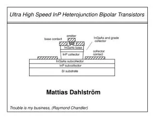
AlN Barrier Regrown Base n+ Emitter Etched Surface Mg Doped Base n- GaN Subcollector n+ GaN Subcollector Sapphire Substrate First GaN HBT • First GaN HBT grown by MOCVD at UCSB in 1998. • Current gain of only 3. • High Acceptor Activation energies in GaN give poor p-type lager. • Thick base (200nm) needed for low base resistance. • Base doping of 4x1019cm-3 resulting in a hole concentration of 1x1018cm-3 McCarthy L S, Kozodoy P, Rodwell M, DenBaars S and Mishra U K 1999 First demonstration of an AlGaN/GaN heterojunction bipolar transistor Proc. Int. Symp. on Compound Semiconductors (Nara, Japan)
First GaN HBT • Regrown Base was needed to make ohmic contacts to the base. • Etch surface was shown to have rectifying effects on contacts. • Nitrogen vacancies created during RIE have donor like characteristics. McCarthy L S,Aluminum Gallium Nitride / Gallium Nitride Heterojunction Bipolar Transistors, PhD Dissertation UCSB 2001.
First GaN HBT • Memory Effect present in all MOCVD grown samples. • Emitter-Base junction placement is erratic. • No memory effect in MBE grown samples and no annealing of p-type layer is required. H Xing, S Keller, Y-FWu, L McCarthy, I P Smorchkova, D Buttari, R Coffie, D S Green, G Parish, S Heikman, L Shen, N Zhang, J J Xu, B P Keller, S P DenBaars and U K Mishra. J. Phys.: Condens. Matter 13 7139 (2001).
Regrown Emitter Structure • Regrown Emitter structure developed. • Eliminates memory effects and etch damage of base. • Base was made thinner (100nm) for improved base transit time. n+ Emitter AlxNy Mg Doped Base n- GaN Subcollector n+ GaN Subcollector Sapphire Substrate
Regrown Emitter Structure Base Contact I-V Abrupt Emitter-Base Junction H Xing, S Keller, Y-FWu, L McCarthy, I P Smorchkova, D Buttari,R Coffie, D S Green, G Parish, S Heikman, L Shen, N Zhang, J J Xu, B P Keller, S P DenBaars and U K Mishra. J. Phys.: Condens. Matter 13 7139 (2001).
RF Performance • Current gains as large as 10 have achieved with this structure. • Early voltages as high as 400V are estimated. • High Emitter-Collector leakage attributed to donor like dislocations in GaN. • Dislocations are present in both HBT structures. H Xing, S Keller, Y-FWu, L McCarthy, I P Smorchkova, D Buttari, R Coffie, D S Green, G Parish, S Heikman, L Shen, N Zhang, J J Xu, B P Keller, S P DenBaars and U K Mishra. J. Phys.: Condens. Matter 13 7139 (2001).
LEO HBT • GaN HBT’s were grown at UCSB via Lateral Epitaxy Overgrowth (LEO)*. • Devices grown over windows exhibited a much larger leakage current than devices grown on the LEO regions. • Gain in both devices was comparable. • Threading Dislocations do not contribute to minority carrier recombination in the base. H Xing, S Keller, Y-FWu, L McCarthy, I P Smorchkova, D Buttari, R Coffie, D S Green, G Parish, S Heikman, L Shen, N Zhang, J J Xu, B P Keller, S P DenBaars and U K Mishra. J. Phys.: Condens. Matter 13 7139 (2001). * McCarthy L, Smorchkova Y, Fini P, Xing H, Rodwell M, Speck J, DenBaars S and Mishra U 2000 BT on LEO GaN Proc. 58th DRC: Device Research Conf. (Denver, CO, 2000)
Improved HBT Common Emitter Operation as high as 330V. Huili Xing, Prashant M. Chavarkar, Stacia Keller, Steven P. DenBaars and Umesh K. Mishra.IEEE ELECTRON DEVICE LETTERS, VOL. 24, NO. 3, MARCH 2003.
Polarization in Nitrides • Polarization fields present in wurtzite structure of nitrides allow for new novel devices. • Polarization charges are created by differences in Polarization Fields. Ga N In [0001] direction: σ = n·(P1-P2) P
Polarization in Nitrides • Two types of Polarization in Nitrides: • Spontaneous Polarization • Piezoelectric Polarization • Gives us two degrees of freedom to determine the polarization charge: • Semiconductor Composition • Layer thickness Debdeep Jena, Polarization induced electron populations in III-V nitride semiconductors Transport, growth, and device applications. PhD Dissertation UCSB (2003)
qΦb Polarization in Nitrides • Electrostatic attraction from polarization charges creates regions of mobile charges. ρ σPOL x 2-DEG σMET
GaN HEMT • Polarization doping has been used in High Electron Mobility Transistors (HEMT). • Polarization doping can increase the effective AlGaN/Gate Barrier. • No need to introduce dopants. • Higher gm at higher voltages. P.M. Asbeck, E.T. Yu, S.S. Lau, W. Sun, X. Dang, C. Shi. Solid-State Electronics 44 (2000) 211±219
Polarization Doping • By grading the Metal composition we can create 3-D bulk doping. x AlxGa1-xN Polarization Charges Graded up 3-DEG GaN ρ
Polarization Doping • Same techniques can be used for p-type doping. • Two configurations of HBT’s result from this: • Emitter up Configuration • Collector up Configuration x Polarization Charges GaN Graded down 3-DHG AlxGa1-xN ρ
n+ Subcollector n- Collector Graded down AlGaN Graded Base n+ AlGaN Emitter Sapphire Substrate Collector up • Using the Collector up configuration polarization doping in base is produced. • Base will produce a dopant free p-type layer improving the base conductivity.
Collector up • As Collector area scales down so does collector current. • Extrinsic emitter base current becomes more dominant. • Minority carriers injected into the base contribute to base current. • Transistor gain is suppressed. P.M. Asbeck, E.T. Yu, S.S. Lau, W. Sun, X. Dang, C. Shi. Solid-State Electronics 44 (2000) 211±219
Collector up P.M. Asbeck, E.T. Yu, S.S. Lau, W. Sun, X. Dang, C. Shi. Solid-State Electronics 44 (2000) 211±219
n+ Emitter Graded up AlGaN Graded Base n- GaN Subcollector n+ GaN Subcollector Sapphire Substrate Emitter Up • Switch crystal orientation. • N-face GaN gives opposite polarization charge allowing p-type doping of the base. • Growth issues are present with N-face GaN
n+ AlGaN Emitter Increasing In InGaN Graded Base n- GaN Subcollector n+ GaN Subcollector Sapphire Substrate Alternative InGaN • Advantages: • Can keep Emitter up structure and still produce the polarization doped p-type base. • InGaN smaller band gap, larger band offset. • Disadvantages: • Spontaneous polarization is almost identical in InN and GaN • Hard to produce polarization charges. • Difficult to grow In rich InGaN. • Higher base transit times.
Conclusions • GaN HBT’s have tremendous potential for high power applications. • p-type conductivity is the limiting factor for all GaN base devices today. • Normally doped GaN HBT’s have been demonstrated, with operational voltages as high as 330V. • Polarization doping gives a promising solution to the p-type conductivity problem. • Growth technique as well as device design must be carefully chosen.