Download
1 / 37
370 likes | 528 Views
ATLAS detector status (I). CERN-RRB-2010-011 Marzio Nessi CERN , 20 th April 2010 . …. since last RRB (12 th October). From 10 th November 2009 to 16 th December the detector has been taking physics data at 450 GeV and 1.18 GeV per beam (single beams and collisions)

E N D
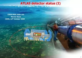
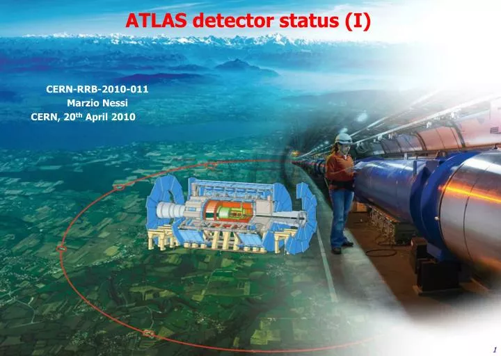
ATLAS detector status (I) CERN-RRB-2010-011 Marzio Nessi CERN, 20th April 2010
…. since last RRB (12th October) • From 10th November 2009 to 16th December the detector has been taking physics data at 450 GeV and 1.18 GeV per beam (single beams and collisions) • From 17th December 2009 to early February 2010 we have been in shutdown mode, but with no internal detector opening. Just access to the external services and to the muon spectrometer • From 28th February 2010 (first 2010 beams injections) we went back to data taking mode with up to now ~400 mb-1 =~ 22M collisions events registered at 3.5 TeV per beam with the entire detector active
Data taking efficiency Stable beam flag Data taking efficiency In the last few weeks our data taking efficiency has been in average around 94%, some time is still lost in turning on the inner detectors once the stable beam flag is set by LHC
Operation resources After the initial learning period we will now operate ATLAS with 55 shifts/day (including Tier0 and distributed computing) at P1 … on top of this, we need ~ 140 x 8 hours-equivalent shifts for experts on call, satellite rooms shifts or remote shifts outside CERN, …… = ~ 150 people involved/day to keep the entire machinery running !
Operation Tasks (OT) sharing • ATLAS operation (detector, data quality and calibration, software, world-wide computing, including all kinds of shifts …) requires ~ 800 FTE(physics is not an OT) • OT are distributed in a fair way across Institutions: proportional to the number of authors • - students get favorable treatment as they are weighted 0.75 • - new Institutions contribute more the first two years (weight factors 1.5, 1.25) • 200 FTE (out of 800 total) are for shifts: ~ 50000 shifts in 2010 (~20 per author) • - 70% CERN-based (Control Room or on-call); 30% remote shifts • - we have recently reduced the number of Control Room shifts by 15% • - as we gain experience less shifts in general, in particular less CERN-based shifts Covered-expected expected FTE requirements and FA contributions reviewed and updated yearly Distribution per FA in 2009 (CERN-based shifts not included) Zero means ok, negative is bad Funding Agency
Shutdown activities • Most of the active detectors components have been switched off for the Xmas break. This has been the occasion for fixing some known problems or upgrade some components in view of the long run in front of us
Shutdown activities • All magnets were left floating in temperature to save operation resources and allow some interventions to fix problem (Shield Refrigerator cryo-filter clogging and Current Lead thermal repair) Cool down of Toroids and Solenoid 28 Jan-11 Feb, 13 days from start at 126K to Cryo_ready flag Phase separator temperature Since then we have established all records on magnets stable operation ! Ramp to 20.4kA Toroid inlet temperature At 4K, start of Helium pumps
Shutdown activities • Fixed a water leak in the caver floor • Consolidated the access structure to the inside of the detector • Continued the installation of the staged EE chambers (barrel forward) • Fixed problems of LV and HV in the muon spectr., fixed elect. problems • Replaced gas filters (MDT), solved gas leaks problems • RPC brought trigger coverage to practically 100% • Got CSC readout chain operational inside the overall TDAQ system • Added redundancy to several infrastructure key elements (electrical and UPS distribution, magnet safety, ventilation, …. ) • Anticipated yearly maintenance on various safety systems • Consolidated gas and detector cooling systems • Installed the first ALFA detector station (1/8), testing methods and time • ……
Pixel tracker p d K Pixel operation • Recovered few modules Non operational 45 modules (2.5 %) • Improved timing, soon ready for high number of bunches • Pixel hits ad vertices in all ATLAS analysis • dE/dx demonstrates how well the pixel-by-pixel calibration works and it has been widely used for all “re-discoveries” • The resolution on the primary vertex in the beam direction would be much worse (40% effect) without for example the b-layer.
Pixel tracker p d K Pixel operation • Recovered few modules Non operational 45 modules (2.5 %) • Improved timing, soon ready for high number of bunches • Pixel hits ad vertices in all ATLAS analysis • dE/dx demonstrates how well the pixel-by-pixel calibration works and it has been widely used for all “re-discoveries” • The resolution on the primary vertex in the beam direction would be much worse (40% effect) without for example the b-layer.
TRT (Transition Radiation Tracker) Barrel End-caps 92% electron pions
LAr Calorimeters (LVPS & OTx) • Today: 58/58 operational FE-LVPS • 5 have lost the redundancy on one voltage line • Backup in preparation • 2 vendors prepared 2 prototypes each • A Source Selection Committee selected the best one • Production Readiness Review 28.04.2010 • Then place the order • Production should be completed by end of 2010 • Setting-up a large test bench at CERN for 16 units • Long term running • Installation next time we open the detector
LAr Calorimeters (LVPS & OTx) • Optical Transmitters Status • For 19 FEB-OTx: VCSEL died between May 2009 & April 2010 • The width of the optical spectrum has been found as an indicator of the weakness • After the measurement was performed (07.2009) all the OTx which died had a narrow OS • There are ~50 remaining OTx with narrow spectrum on the detector • Narrow OS OTx have been kept OFF until mid-March (start of LHC) • OS spectra measured three times since July 2009: stable • Failure rate ~ 3/month . None since 3 weeks! • Future • 2 backup solutions in preparation (choose before the summer) • B1: Replacement by a single VCSEL from a different producer • B2: Replacement by a double VCSEL + layout of double fibers
Tiles Calorimeter Cosmics: Signal /Noise = 29 • 97.3% Tile cells powered ON • 3.2% cells are masked/bad for physics: • 0.5% noise or dig. corrupted data • 2.7% OFF: • - 5 (1.9%) LVPS • - 2 (0.8%) S-drawers We have a solution to be implemented in the next shutdown (needs opening)
Muon spectrometer (CSC flagged as a problem last RRB) • CSC now routinely run in the combined partition • Very stable CSC DAQ operation • Current Read-out rate limit 43 KHz, new versions expected at 53 KHz • CSC tracking commissioning on-going, Ex: good Residual Pool distribution
Muon Spectrometer Performance (precision chambers) Stand alone momentum resolution measured with cosmics Small sectors Large sectors MDT detector coverage very good: 99.7%
TGC trigger timing and efficiency : first results TGC Trigger efficiency vs PT TGC Trigger timing
Today’s major worries • Tiles Calorimeter LV power suppliers failure (5 out of 256 modules since ~8 months) • LAr OTX : additional failure of the light emitting component (VCSEL) on optical transmitters (1 every 2-3 weeks) • Keep the evaporative cooling plant operational (proximity compressor plant). • Magnets shield refrigerator filter clogging (H2O contamination) • Follow up evolution of power supplies failures in the muon spectrometer • Follow up evolution of fragile gas inlets (RPCs) Solutions are being worked out, but it requires a 11 weeks shutdown to make the interventions possible (next Xmas period ?)
Today’s major worries • Tiles Calorimeter LV power suppliers failure (5 out of 256 modules since ~8 months) • LAr OTX : additional failure of the light emitting component (VCSEL) on optical transmitters (1 every 2-3 weeks) • Keep the evaporative cooling plant operational (proximity compressor plant). • Magnets shield refrigerator filter clogging (H2O contamination) • Follow up evolution of power supplies failures in the muon spectrometer • Follow up evolution of fragile gas inlets (RPCs) A new evaporative cooling plant is being evaluated and is under study A major upgrade of possible single point of failure is being pursued. It should be ready by 2012
ID evaporative cooling plant problems A new problem was found in March on 2 out of the 7 compressors, which forced us to a major repair once more …. But we managed to keep the plant nevertheless operational (with 4 units) …. No impact on physics! Important traces of debris impacts have been found on the cylinder and piston head. The origin of the failure and the debris has been identified in the suction valve of the first stage of the compressors.
ID evaporative cooling plant : 2 solutions under evaluation Full thermo-siphon solution which uses gravity to establish correct pressure conditions, no active mechanical components …. But it requires a large chiller plant on surface to condensate the liquid! condenser Low temperature chiller (-70 C) liquid tank pneumatic valve Surface pneumatic valve USA15 others manual valve 4 liquid lines PR Heater thermal screen USA15 UX15 dummy load pixel manual valve 4 gas lines 6 X SCT BPR manual valve
ID evaporative cooling plant : 2 solutions under evaluation Hybrid solution where condensation is helped by a new generation of compressors (vibrations and oil free, magnetic bearings) …. It requires a standard chiller plant on surface (-10C)! One of such compressors is now under test at CERN! condenser Standard Chiller liquid tank pneumatic valve Surface pneumatic valve USA15 others manual valve 4 liquid lines PR Heater thermal screen USA15 UX15 dummy load pixel manual valve 4 gas lines 6 X SCT BPR manual valve
ID evaporative cooling plant : Thermo-siphon solution R&D • Tests of a mini thermo-siphon in bldg 191 successfully finished : • 13 meters height, silent no mechanical stress • Stable operation at -22 oC • -30 oC reached • Start up procedure and limitations well understood • Next step : installation and test at Point1 • A full (geometrical) scale thermo-siphon circuit should allow us to study thermo-dynamics and time constants and to study blends C3F8-C2F6 • Vertical piping installed from SH1 to USA15 level 3 Our goal : ready for 2012 shutdown
Magnet system consolidation work • Most shut-downs are related to cryogenics : • Today we have 1 main compressor in the Main Refrigerator, when it breaks we are down for 9-12 months. Cure: install redundant main compressor for the Main Refrigerator • We are experiencing several problems of filter clogging (water contamination). To solve the problem we have just identified an air dryer to install in the next few months • The main Helium pump represents another single point of failure, solutions are been worked out, this adds to other consolidation needs on vacuum, controls, ….. All must be ready for 2012
Today’s major worries • Tiles Calorimeter LV power suppliers failure (5 out of 256 modules since ~8 months) • LAr OTX : additional failure of the light emitting component (VCSEL) on optical transmitters (1 every 2-3 weeks) • Keep the evaporative cooling plant operational (proximity compressor plant). • Magnets shield refrigerator filter clogging (H2O contamination) • Follow up evolution of power supplies failures in the muon spectrometer • Follow up evolution of fragile gas inlets (RPCs) • A new potential problem of hot cells in the LAr Had endcaps is being investigated
What is next on the detector side ? • The detector is ready for a long run in 2010/2011. It is performing well • We have solutions for the problems we are facing. To fix the Calorimeters % problems we will need access and therefore enough time to open and close the detector (~11 weeks) • A consolidation of the cryogenics system and of the evaporative cooling plant is foreseen for the long shutdown in 2012. We are actively preparing it. • We have learned enormously on the way to operate the detector. Now we can start to optimize the necessary resources, in particular the manpower needs for operation!
… and on the medium/long term ? (upgrade/consolidation) We are developing plans in 3 phases: • Phase 0: when we will fix all problems we know (cryogenics, evaporative cooling plant, calorimeters LVPS, optical transmitters, various single points of failure,….). We will also substitute the Fe beam pipe with a lighter one (Al or Al/Be) in order to minimize radiation backgrounds 2012 LHC shutdown • Phase 1: when we have collected enough statistics (at least 50 fb-1) and we will feel ready to make changes to the detector itself. We want the best possible detector for the bulk of the data we will take at LHC (~300fb-1). We need then a detector capable of ultimate Luminosity. We can improve on b-tagging and on the sharpness of the LVL1 trigger • Phase 2: we will then prepare the detector for the sLHC challenge. We will need to construct and install a new ID (after 300-400 fb-1)
Our strategy ! Be ready for sLHC New ID + solve LAr end-caps problems • - Be ready for ultimate Luminosity • - Insert new pixel b-layer • Upgrade various systems for a better and sharper LVL1 trigger Int. Luminosity Consolidation + new beam pipe We need to input our requirements in the overall LHC optimization plans Phase -0 Phase -1 Phase -2 year Shutdown requirements : Phase-0 : 12-14 months (defined by the LHC consolidation) Phase-1 : 8-9 months (time necessary to install at least the new pixel b-layer) Phase-2 : 18-20 months to install and debug the new ID detector
Our strategy for Phase-1 • - Be ready for ultimate Luminosity • - Insert new pixel b-layer • Upgrade various systems for a better and sharper LVL1 trigger Int. Luminosity Phase -0 Phase -1 Phase -2 year • We are preparing projects to be ready for phase-1 : • The first one is the insertable pixel b-layer (IBL). We will be ready at the end of 2014, in case the pixel detector will start showing problems. We will then install it as soon as a long shutdown can be scheduled. The construction is starting. We have drafts of a TDR and MOU • We are in the process of defining other projects, which can be organized in a way similar to the IBL. Most of these projects relate to an upgrade of the trigger system (more detector trigger granularity in the muon system, new generation of trigger hardware, a fast track processor, ….)
IBL (insertable B layer) Detector • The present 7m long section of the beam-pipe will be cut (flange too big to pass inside the existing pixel) and extracted in situ: • The new beam-pipe with the IBL will be inserted at its place. PP1 Collar Sealing service ring Alignment wirers IST IBL Support Tube IBL Staves Existing B-layer IBL (Staves)
Technical Status of the IBL Project FE-I4 – New pixel front-end chip for IBL • 20 x 19 mm2 real-estate, more that 70 M-transistors, largest HEP chip ever. • 2 year design work for a team of ~15 engineers + several physicists from 5 laboratories. • Three design reviews: 17/3/2008, 3-4/11/2009, 16/4/2010 - submission to IBM: 17/5/2010 Sensor prototypes for FE-I4 under processing – 3 technologies considered: Planar Sensors, 3D Sensors, Diamonds. • Expected sensors bump-bonded to FE-I4 for next fall IBL Layout finalised – 14 staves with 32 FE-I4 chip modules at R=3.2 cm Stave baseline (following last December review’s recommendations) • Low density carbon foam (ρ = 0.2 g/cm3), thin wall titanium cooling pipe (d=2mm), CO2 cooling. • Fitting and permanent cooling joints under prototyping. • FEA analysis on going, thermal figure of merit measurement on samples Mechanical design of the whole IBL detector • 3D model and FEA for the whole detector on going. • Installation mock-up under construction in bld.180 at CERN. • Internal electrical services, flex hybrid in prototype phase. New ROD/BOC (off-detector readout). • Modernized version of the Pixel VME ROD – more compact (x4 more channels/board) increased performance, large reduction of component count with state of the art FPGA technology.
Memorandum of Understanding IBL Memorandum of Understanding (MoU) • BetweenThe ATLAS COLLABORATION, andFunding Agency/Institution of the ATLAS Collaboration IBL MoU – Steps toward project shaping: • “IBL Kick-off” meeting (8/7/2009) – Institutes express their interest in the IBL based on project WBS (Workpackage Breakdown Structure). • Sharing of Resources (draft) discussed in the (interim) Institute Board (1/3/2010) – Contribution to the Cost presented to the National Contact Physicists in ATLAS (ATLAS NCP meeting – 25/2/2010). IBL interim MoU • Ad Interim MoU until sensor technology is chosen (Planar Silicon / 3D Silicon / Diamond) - Decision on sensor technology (early 2011) – Sensor R&D and IBL communities work in tight collaboration to finalise a design matching IBL specification. • Consolidate interest of Institutes and availability of funds
MOU Annex 4: Tentative Contribution to IBL Technology options refer to supplementary costs that are sensor technology specific and will be known before the definite MoU takes effect. So far, France, Italy and US have requested their shares to be moved from M&O B to Project part. Note: the numbers in the table "are not final, nor are the suggested financial contributions yet firm, but are meant for a common overall discussion.”
Phase-2 Upgrade (sLHC) • We have centrally organized a vigorous R&D program for most of the technology we have to act on (more then 20 active R&D projects have been approved and are operational) • The optimization of the layout of the new Inner Detector is at the moment the major concern. Most of the work is on simulation! The process is ongoing • The first step of detailed engineering has started, we are now facing a new phase where we need to decide on the construction of large prototypes (staves, modules, services layout, support structures,….) to demonstrate feasibility. The time needed for mass production is probably around 7-8 years, once the project is fully defined