Download
1 / 22
220 likes | 307 Views
Capture/Phase Rotation for Neutrino Factory and Muon Collider Update. David Neuffer Cary Yoshikawa February 2008. 0utline. Introduction ν -Factory Front end Capture and Φ -E rotation High Frequency buncher/rotation update Study 2B ν -Factory Shorter version To Cool or not to cool

E N D
Capture/Phase Rotation for Neutrino Factory and Muon ColliderUpdate David Neuffer Cary Yoshikawa February 2008
0utline • Introduction • ν-Factory Front end • Capture and Φ-E rotation • High Frequencybuncher/rotation update • Study 2B ν-Factory • Shorter version • To Cool or not to cool • ν-Factory→μ+-μ- Collider • Mucool Note 520 • Discussion
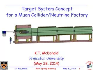
Solenoid lens capture • Target is immersed in high field solenoid • Particles are trapped in Larmor orbits • B= 20T -> ~2T • Spiral with radius r = p/(0.3 Bsol) =Bρ/B • Particles with p < 0.3 BsolRsol/2 are trapped • p,max < 0.225 GeV/c for B=20T, Rsol = 0.075m • Focuses both + and - particles
High-frequency Buncher and φ-E Rotator • Form bunches first • Φ-E rotate bunches
Study2B June 2004 scenario (ISS) • Drift –110.7m • Bunch -51m • (1/) =0.008 • 12 rf freq., 110MV • 330 MHz 230MHz • -E Rotate – 54m –(416MV total) • 15 rf freq. 230 202 MHz • P1=280 , P2=154NV = 18.032 • Match and cool (80m) • 0.75 m cells, 0.02m LiH • Captures both μ+ and μ- • ~0.2μ/(24 GeV p)
Study 2B ICOOL simulation (NB=18) 500MeV/c s = 1m s=109m Drift 0 500MeV/c s= 216m s=166m Bunch Rotate 0 60 -40
Features/Flaws of Study 2B Front End • Fairly long system ~300m long (217 in B/R) • Produces long trains of ~200 MHz bunches • ~80m long (~50 bunches) • Transverse cooling is ~2½ in x and y, no longitudinal cooling • Initial Cooling is relatively weak ? - • Requires rf within magnetic fields • in current lattice, rf design; 12 MV/m at B = ~2T, 200MHz • MTA/MICE experiments to determine if practical • For Collider (Palmer) • Select peak 21 bunches • Recombine after cooling • ~1/2 lost 500 MeV/c -40 60m
Shorter Bunch train example • Reduce drift, buncher, rotator to get shorter bunch train: • 217m ⇒ 125m • 57m drift, 31m buncher, 36m rotator • Rf voltages up to 15MV/m (×2/3) • Obtains ~0.26 μ/p24 in ref. acceptance • Slightly better ? • ~0.24 μ/p for Study 2B baseline • 80+ m bunchtrain reduced to < 50m • Δn: 18 -> 10 500MeV/c -30 40m
Further iteration/optimization • Match to 201.25 MHz cooling channel • Reoptimize phase, frequency • f = 201.25 MHz, φ = 30º, • Obtain shorter bunch train • Choose ~best 12 bunches • ~ 21 bunch train for Collider at NB= 18 case ~12 bunches (~18m) • ~0.2 μ/pref in best 12 bunches • Densest bunches are ~twice as dense as NB = 18 case
Details of ICOOL model (NB=10) • Drift– 56.4m • B=2T • Bunch- 31.5m • Pref,1=280MeV/c, Pref,2 =154 MeV/c, nrf = 10 • Vrf 0 to 15MV/m (0.5m rf, 0.25m drift) cells • 360 MHz 240MHz • -E Rotate – 36m – • Vrf = 15MV/m (0.5m rf, 0.25m drift) cells • NV = 10.07 (240 -> 201.5 MHz) • Match and cool (80m) • Old ICOOL transverse match to ASOL (should redo) • Pref= 220MeV/c, frf = 201.25 MHz • 0.75 m cells, 0.02m LiH, 0.5m rf, 16.00MV/m, φrf =30° • Better cooling possible (H2, stronger focussing)
Simulations (NB=10) s = 1m s = 89m Drift and Bunch Rotate 500 MeV/c s = 219m s = 125m Cool 0 30m -30m
Even Shorter Bunch train ~(2/3)2 • Reduce drift, buncher, rotator to get even shorter bunch train: • 217m ⇒ 86m • 38m drift, 21m buncher, 27m rotator • Rf voltages 0-15MV/m, 15MV/m (×2/3) • Obtains ~0.23 μ/p in ref. acceptance • Slightly worse than previous ? • 80+ m bunchtrain reduced to < 30m • 18 bunch spacing dropped to 7 500MeV/c -20 30m
Details of ICOOL model (NB=7) • Drift– 37.7m • B=2T • Bunch- 21m • Pref,1=280MeV/c, Pref,2 =154 MeV/c, nrf = 7 • Vrf 0 to 15MV/m (0.5m rf, 0.25m drift) cells • 350 MHz 230MHz • -E Rotate – 27m – • Vrf = 15MV/m (0.5m rf, 0.25m drift) cells • NV = 7.1 (230 -> 204 MHz) • Match and cool (80m) • Old ICOOL transverse match to ASOL (should redo) • Pref= 220MeV/c, frf = 201.25 MHz • 0.75 m cells, 0.02m LiH, 0.5m rf, 15.25MV/m, φrf =30°
-Factory Cooling Channel • Cooling is limited: • LiH absorber, β≅ 0.8m • from ~0.018 to ~0.0076m in ~80m • εeq 0.006m • Could be improved • H2 Absorber (120A) or smaller β • ~0.0055 • εeq 0.003m Before After LiH cooling +0.4m -0.4m After H2 cooling
LiH Cooling Channel (Study 2A) εT : ~0.018 0.0076 Acceptance increase ~2× over 80m εeq 0.006m Study 2B final Increase ~1.7 in cooling channel Initial cooling is in Be windows in rotator Gaseous cooling (H2; 120Atm) ~factor of 2 smaller εeq (0.003) Similar to ~ 2× smaller β* can cool to ~0.0055 in 80m Halo reduced also .. Improvement from no-cooling is 2.5 to 3 × (~0.34/0.12)=2.8 Cooling Comments…
Example: NB = 10, H2 cooling 0.2 Transverse emittance εt,,N (m) μ/p (8GeV) All μ’s 1.5 ZM 0.1 μ/p within acceptance 0
Discussion • Guess: Optimum is NB ≈ 10 • (for both collider and ν-Factory) • As many μ/p as baseline in more compact bunch train • Length is ~1/2 × Study2B / ISS example • 215m -> 125m • Shorter buncher/rotator is cheaper • cost × ~3/4 ?? …. • Better cooling would be desirable • H2 absorber and/or stronger focussing • Assumed for these scenarios: • ~15 MV/m at B 2T and f 200MHz is practical
Adapt to project X parameters • Consider 8 GeV initial beam • New beam from Mars simulation • B=20T, Hg-jet target, 8-GeV p-beam • ~60cm long target region, ~MERITgeometry • 1 to 3 ns rms bunch length • Weighted distribution • Express yield in “E-independent” units • 0.2μ/(24GeV p)=1.042 Zμ/year-MW (ZyM) • (1021μ/ MW-year) , where year is 2×10⁷ s • Study 2B is ~0.885 ZyM … (or ZM =ZisMans ?)
ZyM-ology – ICOOL results • Place 8GeV in NB=10 lattice • LiH lattice • Yield is 1.278 ZM (εt <0.03,εL<.2,1ns) • (0.0814 μ/p) • 1.134ZyM @(εt <0.03,εL<.15,1ns) • Compare w/ 24 GeV NB=10 • St2 ref. beam: 1.375 ZM (3ns) • St2A ref. beam: 1.156 ZM • St2 ref. beam: 1.521 ZM (1ns) • More sensitive to bnx length • Change to H2 cooling • ~1.67 ZM (εt <0.03,εL<.2,1ns) 8GeV • ~1.5 ZM(εt <0.03,εL<.15,3ns)
Conclusions • Can use high-frequency capture to obtain bunch train for ν-Factory → μ+-μ- collider • (~10 to 14 bunches long at 200MHz ) • Recombine after cooling for collider mode • Questions • Is ~200 MHz optimal? • ~15 MV/m at B 2T and f 200MHz is OK? • Is ~12 bunches OK for Collider scenario • To Do: • Turn into detailed design for IDS ??