Download
1 / 14
140 likes | 266 Views
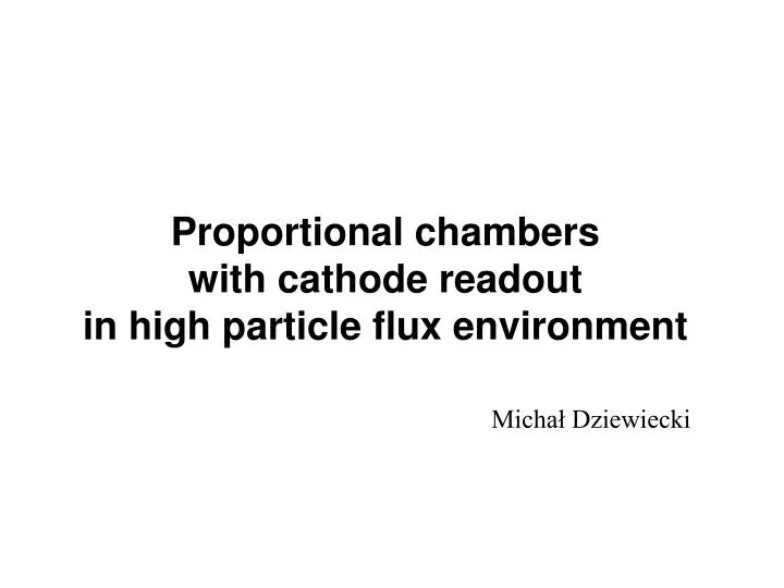
Proportional chambers with cathode readout in high particle flux environment. Michał Dziewiecki. The GSI. Temperature T (MeV). Density ρ / ρ 0. GSI – a heavy ion research facility, Darmstadt, Germany FAIR – Facility for Antiproton and Ion Research –

E N D
Proportional chambers with cathode readout in high particle flux environment Michał Dziewiecki
The GSI Temperature T (MeV) Density ρ/ρ0 GSI – a heavy ion research facility, Darmstadt, Germany FAIR – Facility for Antiproton and Ion Research – a futureheavy ion accelerator centre CBM –Compressed Baryonic Matter Experiment – Its main aim will be to obtain a quark-gluon plasmaat very high nuclear matter density but moderate temperatures. It can be achieved by colliding heavy (Au) ions against an Au target.
Silicon tracker TRT 1 (Transition Radiation Tracker) TRT 2 TRT 3 Heavy ion (Au) beam 25 AGeV Beam hole Target (0.3mm Au) RICH (Ring Imaging Cherenkov Detector) Detector setup of CBM TRTs: 1st: 5.8 x 3.9 m 2nd: 8.7 x 5.8 m 3rd: 11.6 x 7.7 m Each TRT module consists of 6 independent detectors. Total TRTs’ area: 500 m2
TRT at CBM • Large Area Tracker (23-89 m2) • Main goal particle selection The aim is to extract high energy electrons from a huge amount of pions crossing the detector plane. Requested pion suppression factor - 300 The detector can be also used for particle track reconstruction. • Total amount of 18 detectors 3 modules, 3 double detectors per module, inclined at angle of 0, +10 and –10 degrees vs the vertical orientaton • Main problem: high particle flux High collision multiplicity (300-400 particles per collision), up to millions of collisions per second
High energy electron Electron + photon beam Radiator (a set of foils) Straw chamber TRT operation principle • Each transition of a high energy particle between radiator mediums (foil and air) invokes X-ray emission • The X-ray photons (and the particle itself) are detected through straw detectors • Pions (at relatively low energies) do not generate X-rays – this feature lets us determine what kind of particle crossed the detector. CBM: Radiator: 250-300 foils Straws: 3-6mm diameter, metalized Kapton
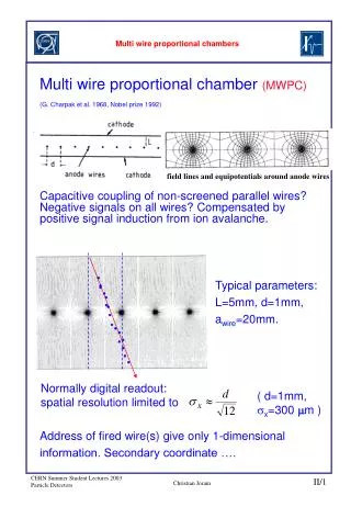
Anode (+HV) Cathode (GND) Gas Charged particle or photon Avalanche Ionization cluster Proportional counter –single section of a straw chamber Charged particle producesionization clusters A photon produces only one, but relatively large cluster Electrons drift to the anode along the potential gradient Near the anode the electric field is strong enough to cause a secondary ionization (electron avalanche). Resultant ions drift to the cathode, causing measurable current flow through the counter.
x Amplified signal time Δt = f(x) Position estimationAnode readout • The time between particle appearance and signal registration is utilized. • The coordinate perpendicular to straw axis is measured • There is a left-right indetermination problem • A TAC (Time to Amplitude converter) or TDC (Time to Digital converter) circuitry is used • An additional fast detector (trigger) is necessary to generate TAC start signal
Straws Cathode strips Position estimationCathode readout • We take advantage of signal differences between the cathode strips. • The coordinate parallel to straw axis is measured • If two particles cross the detector in the same (or near) time, the readings of the positions will disturb each other – it’s calledfrequency effects. It’s one of the most significant problems by cathode readout.
Pad readoutan enhancement of cathode readout • Cathode strips are split to relatively short pads • Errors induced by frequency effects are lower • There occurs a partial separation along the axis perpendicular to straws. • The disadvantage of this solution is a very big count of analog channels • The entire count of TRT pads in the CBM experiment can reach 1 million!
Pad readoutand frequency effects • Each ionization causes a signal on every pad • Largest errors are caused by ‘near ionizations’ in the area of measured pads and in theirneighbourhood. • Frequency effects manifest as random errors on calculated position • There are two ways of reducing these errors: • Decreasing pad dimensions • Moreover, we must reduce the diamater of straws to decrease effective pad dimensions. This leads to reduction of detection efficiency. • Speeding up the electronics, thus we can enhance the time resolution The ADCs at CBM will be working at 20MHz sampling rate, thus the pulse width can not be shorter than 200ns.
20 18 16 14 12 Samples count 10 8 6 4 2 0 -0.15 -0.1 -0.05 0 0.05 0.1 Error[mm] Exemplary error distribution (central part) Computer simulation A Monte-Carlo simulation was executed in order to analyze the problem • All steps of the signal development were considered: • cluster generation • electrons drift • gas amplification • signal forming at cathode • signal shaping at the amplifier • The simulator calculated the difference between computed and real position of particles • Results were presented in form of error distribution graphs
Exemplary error distribution 101 100 error [mm] 5x50x2.5mm, 2100cz/mm^2*s 10-1 10-2 2 4 6 8 10 12 14 16 18 20 22 Particle flux[part·mm-2·s-1] ·100 Guarateed accuracy for 80, 90 and 95% of particles Simulation resultsand conclusions • The problem long error distribution tails (see figure) • Error values spread from 0 to few mm, dependig on pad width; the tails are effect of „near ionizations”, where the readings of two avalanches run into one another. • Large tails cause that relatively many readings are too inaccurate to be accepted. • Predetermined accuracy (200 μm) will be hard to achieve.
BLR ADC BLR ADC BLR ADC BLR ADC HARDWARE SOFTWARE Pulse detection Software BLR Signal oversampling Peak detection HDD Position calculation Experimental verification of obtained results A small model of chamber is being built to verify the simulation results. • A 40·40cm multiwire proportional chamber with pad readout • Four-channel amplifier – shaper – base line restorer – ADC circuitry • 250 ns pulse shaping, 20 MHz max sampling rate • A PC for data acquisition and processing • A multi-threaded Visual C++ program for better HT-processors utilization.