Download
1 / 26
270 likes | 522 Views
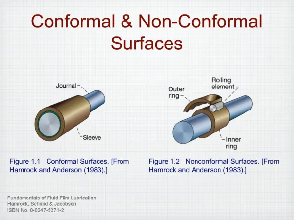
Active Control of Separation on a Wing with Conformal Camber. David Munday and Jamey Jacob Department of Mechanical Engineering University of Kentucky 8 January 2001. The 39 th Aerospace Sciences Meeting and Exhibit American Institute of Aeronautics and Astronautics. Outline. Motivation

E N D
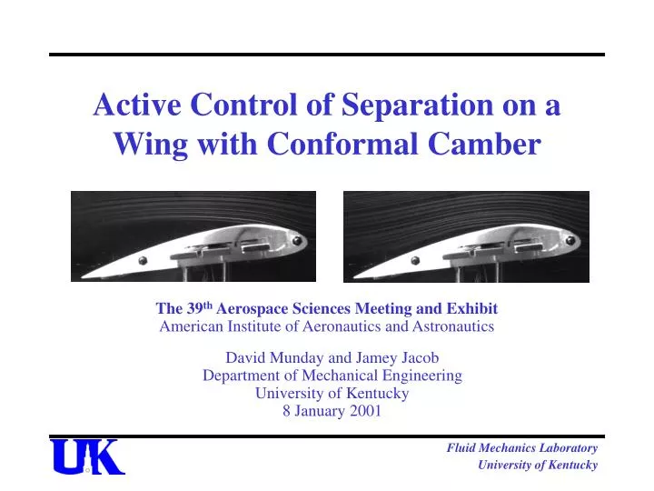
Active Control of Separation on a Wing with Conformal Camber David Munday and Jamey Jacob Department of Mechanical Engineering University of Kentucky 8 January 2001 The 39th Aerospace Sciences Meeting and Exhibit American Institute of Aeronautics and Astronautics Fluid Mechanics Laboratory University of Kentucky
Outline • Motivation • Flow Control • Adaptive Airfoils • Adaptive Wing Model • Experimental results • Conclusions • Further work Fluid Mechanics Laboratory University of Kentucky
Motivation • μAVs Re = 104 - 105 • UAVs Re = 105 - 106 • High Altitude • Other atmospheres (Mars) Fluid Mechanics Laboratory University of Kentucky
Airfoil Performance • L/D reduced by more than an order of magnitude as Re falls through 105 Figure from McMasters and Henderson Fluid Mechanics Laboratory University of Kentucky
Laminar Separation Bubble • Adverse Pressure gradient on a laminar flow causes separation • Transition occurs. Fluid is entrained and turbulent flow re-attaches Figure from Lissaman Fluid Mechanics Laboratory University of Kentucky
Flow Control • Any method which can modify the flow • Can be passive or active • Active flow control can respond to changes in conditions • Requires energy input • Active flow control is not a mature technology • Shows promise Fluid Mechanics Laboratory University of Kentucky
Active Flow Control • Constant sucking or blowing • Intermittent sucking and blowing (synthetic jets) • Wygnanski, Glezer • Suggests existence of “sweet spots” in frequency range • Mechanical momentum transfer • Modi, V. J. • Change of the shape of the wing (Adaptive Airfoils) Fluid Mechanics Laboratory University of Kentucky
Adaptive Airfoils • Can change shape to adapt to flow • Simple examples: Flaps, Slats, Droops • Move slowly, quasi-static • Change shape parameter (usually camber) to adapt to differing flight regimes • Rapid Actuation • Can adapt to rapid changes in flow condition • May produce the same sort of “sweet spot” frequency response as synthetic jets Fluid Mechanics Laboratory University of Kentucky
Some Adaptive Wing Research • DARPA smart wing • torsion control of entire wing using internal actuators • DDLE wing • rapid change in leading edge radius using mechanical actuator • micro Flaps - MITEs (Kroo et. al.) • multiple miniature trailing edge flaps with fixed displacement Fluid Mechanics Laboratory University of Kentucky
Piezoelectric Actuation • Rapid actuation requires either large forces or light actuators • Piezo-actuators are small and light • They are a natural choice for μAV designs Fluid Mechanics Laboratory University of Kentucky
Previous Work • Pinkerton and MosesA Feasibility Study To Control Airfoil Shape Using THUNDER, NASA TM 4767 Fluid Mechanics Laboratory University of Kentucky
Adaptive Wing Construction • NACA 4415 • well measured, room for internal actuator placement • Modular (allows variation in aspect ratio) • Multiple independent actuators • Flexible insulating layer and skin Fluid Mechanics Laboratory University of Kentucky
Adaptive Wing Construction • Airfoil Profiles • predicted prior to construction using given actuator placement and full range of actuator motion • actuator displacement increases maximum thickness and moves point of maximum thickness aft Fluid Mechanics Laboratory University of Kentucky
Wing Construction Base 4415 With Cutout With mount-block With Actuator With spars Fluid Mechanics Laboratory University of Kentucky
Adaptive Wing Module • A Single Module Fluid Mechanics Laboratory University of Kentucky
Testing Overview • Static model force measurements • L/D enhancement using fixed actuator locations • Static model PIV • separation control using fixed actuator locations • Dynamic model force measurements • L/D enhancement using oscillating actuator motion • Dynamic model Flow Visualization • flow control using oscillating actuator motion Fluid Mechanics Laboratory University of Kentucky
Static Model Force Measurements • Wind tunnel tests • L/D declines as actuator displacement decreases then increases as maximum displacement is reached at high AoA Corrected for Blockage as per Barlow, Rae and Pope, 1999 Fluid Mechanics Laboratory University of Kentucky
Static Model PIV Separation Fluid Mechanics Laboratory University of Kentucky
Dynamic Model • Oscillating upper surface • scanning LDS at 1 inch/sec with 1 Hz oscillation Plot of displacement -vs- time as a distance transducer scans the model. Oscillations can be seen. Units are mV -vs- seconds. Fluid Mechanics Laboratory University of Kentucky
Dynamic Model Force Measurements • So far we have only tested at a Re of 25,000 • At this Re the forces are quite light • They are lost in the noise • We expect to have force measurements for higher Re • Present model has protrusions on lower surface where the skin attaches • Next generation model will have the attachment hardware recessed Fluid Mechanics Laboratory University of Kentucky
Dynamic Model Flow Visualization • Flow Visualization is by the smoke wire technique • As described in Batill and Mueller (1981) • A wire doped with oil is stretched across the test section • The wire is heated by Joule heating and the oil evaporates making smoke trails • Limited to low Re • Limit due to requirement for laminar flow over wire • Limited to a wire diameter based Red < 50 Fluid Mechanics Laboratory University of Kentucky
Dynamic Model Flow Visualization α = 0˚ Actuator Fixed Actuation 15 Hz Fluid Mechanics Laboratory University of Kentucky
Dynamic Model Flow Visualization α = 9˚ Actuator Fixed Actuation 45 Hz Fluid Mechanics Laboratory University of Kentucky
Conclusions • Large static displacement of the actuator shows some improvement in L/D • Oscillation of the actuator has a pronounced effect on the size of the separated flow • The response to this oscillation does show a “sweet spot” where separation is reduced maximally • 15 Hz for 0˚ • 20 to 60 Hz for 9˚ with a maximum at 45 Hz Fluid Mechanics Laboratory University of Kentucky
Further Work • Expand the range of Re • Force measurements of Dynamic Mode • effect on L/D • PIV measurements of Dynamic Mode • flow control • Phase average PIV data • Examine behavior with artificial turbulation • Compare gains in performance with power required Fluid Mechanics Laboratory University of Kentucky
Questions? Fluid Mechanics Laboratory University of Kentucky