Download
1 / 35
350 likes | 497 Views
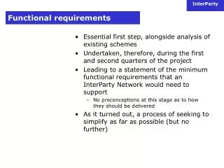
Real Time Controller Functional Requirements. Don Gavel & Marc Reinig UCO Lick, laboratory for Adaptive Optics. Keck NGAO Team Meeting December 13, 2007 Videoconference. Outline. Status Issues Plans. Status. We have an architecture that meets the performance requirements

E N D
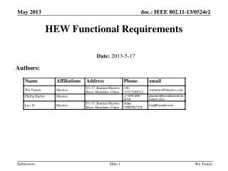
Real Time Controller Functional Requirements Don Gavel & Marc Reinig UCO Lick, laboratory for Adaptive Optics. Keck NGAO Team Meeting December 13, 2007 Videoconference
Outline • Status • Issues • Plans NGAO Real Time Controller FRD
Status • We have an architecture that meets the performance requirements • 9 LGS/WFS (64x64) • 2 Tip/Tilt WFS • 1 T/T-focus-astigmatism WFS • 1 Truth WFS • 5 DM’s (with T/T) (64x64) • 1 Woofer • <500µSec from receipt of image to commands received at the DM • Scalable to larger problems • We have validated the software in the lab and through simulation NGAO Real Time Controller FRD
Architecture– Hardware and Software – NGAO Real Time Controller FRD
NGAO System Context Block Diagram(DRAFT) NGAO Real Time Controller FRD
NGAO System Context Block Diagram(DRAFT) cont. NGAO Real Time Controller FRD
Interface to SRT System • SRT controls all aspects of RTC - Ethernet • There will be a non-RT Linux PC controlling the RTC • Interface to the SRT will be Ethernet between the SRT and the RTC control PC • Load and read the RTC code for all operations • Load and read the RTC HW configuration • Telemetry streams to monitoring, PSF, etc - Ethernet • Interface between the RTC and the high-speed disk arrays for diagnostic data - Fiber Link or equivalent NGAO Real Time Controller FRD
NGAO RTC System Context Block Diagram(DRAFT) NGAO Real Time Controller FRD
Pre Pre - - Back Back - - Post Post - - - - 1 1 FT FT FT FT X X condition condition propagate propagate condition condition Volumetric Volumetric Aperture Aperture d d OPD OPD - - + + estimates estimates WFS WFS Forward Forward - - - - 1 1 FT FT FT FT X X data data propagate propagate Aperture Aperture Tomography Is Part of a Larger System– With characteristics that lend themselves to a similar solution – Kolmogorov filter Guide star height Layer heights Independent parallel streams of parallelizable processes More independent parallel streams! NGAO Real Time Controller FRD
A Systolic Array NGAO Real Time Controller FRD
Data Rate and Location Nasmyth Nasmyth Computer Room Fiber Link or equivalent (>160MB/Sec each) Telemetry Data Diagnostic Data (To Disk) (>1 GB/Sec) Nasmyth NGAO Real Time Controller FRD
Telemetry and Diagnostics Streams Telemetry (Low bandwidth, on-line monitoring) (>1Hz) • Set and read the telemetry rate for each data stream • Set and read the data streams that are enabled for telemetry • Centroids • Residual tomography error • DM commands, including uplink • Tip/Tilt commands Diagnostics (High bandwidth, stored to disk) (full frame rate) (Could be > 1GB/Sec) • Set and read the diagnostic rate for each data stream • Set and read the data streams that are enabled for diagnostics • Centroids • Residual tomography error • Raw layer information • DM commands, including uplink • Collapsed layer information • Tip/Tilt commands NGAO Real Time Controller FRD
RTC Software Flow NGAO Real Time Controller FRD
Tomography Basic Loop NGAO Real Time Controller FRD
Forward Propagation NGAO Real Time Controller FRD
Calculate Error NGAO Real Time Controller FRD
Back Propagate NGAO Real Time Controller FRD
Calculate New Estimate NGAO Real Time Controller FRD
WFS Control Commands Camera • Set and read the camera frame rate • Set and read the camera pixel rate • Set and read the camera gain Centroiding • Load the dark pattern • Load pixel gain pattern • Set and read the threshold level • Set and read the centroiding algorithm • Load and read the centroid weights • Load and read the reference centroids • Load and read the centroid offsets • Set and read pixel offsets for the camera image • Set and read the guidestar mode (NGS or LGS) for any WFS • Load and read centroid non linearity tables NGAO Real Time Controller FRD
Tomography Control Commands • Load and read the cone-effect scaling array for any guide star or target • Load and read the sky position for any guidestar or target • Load and read the Kolmogorov filter array • Load and read the pre-conditioning arrays • Load and read the tomography loop gain arrays • Load and read the tomography bailout value • Load and read the Cn2 values for all layers • Load and read the wind array for all layers NGAO Real Time Controller FRD
DM and Tip/Tilt Control Commands • Load and read the layer-to-DM collapse arrays • Load and read the DM command matrixes and non linearity lookup tables for open and closed loop control • Set and read DM open/closed loop mode • Set and read the Tip/Tilt command matrixes NGAO Real Time Controller FRD
Calibration Capabilities • Create a system matrix for any DM • Set the number of frames to use when creating the system matrix • Clear the DM of any manually set values • Calibrate science target DMs in MOAO • Woofer • Tweeter • Force an arbitrary camera image for any WFS • Force an arbitrary centroid output for any tomography WFS input • Force an arbitrary layer pattern to be used by the DM command module • Send an arbitrary pattern to any DM • Save the current centroid positions as an reference centroid file (averaged over a settable number of frames) NGAO Real Time Controller FRD
System Diagnostics Capabilities • Read all chip temperatures • Read system temperatures at various predetermined locations • Monitor chip and system fan operation • Set and read temperature alarm trip levels NGAO Real Time Controller FRD
Reliability and Reparability • Graceful degradation • Spares requirement • MTBF • Self Healing (SEU) NGAO Real Time Controller FRD
Physical Characteristics • Size • <20 m3 • Weight • TBD • Location • WFS and DM Drive are on the Nasmyth • RTC and High Speed Disk array are in the computer room • Power • <20KW NGAO Real Time Controller FRD
Issues Remaining • Determine Single Event Upset (SEU) rate from Gamma/Cosmic rays • Verify detection and recovery scheme NGAO Real Time Controller FRD
Plans • Complete FRD • Finish writing report • Validate SEU issues NGAO Real Time Controller FRD
Backups NGAO Real Time Controller FRD
Data Rate Work Sheet NGAO Real Time Controller FRD
Sample Code to Configure the Hardware– Simple ALU – modulealu4 ( input_a, input_b, output_c, ctrl_0, ctrl_1, ctrl_2,ctrl_3, clr, clk ); inputctrl_0, ctrl_1, ctrl_2, ctrl_3; input [15:0] input_a, input_b; output [31:0] output_c; inputclr, clk; wire [3:0] ctrl; reg [31:0] output_c; assign ctrl = {ctrl_3, ctrl_2, ctrl_1, ctrl_0}; parameter ADD = 4'b1001; parameter MUL = 4'b0001; parameter NOP = 4'b1000; always @(posedge clk or posedge clr) begin if (clr) output_c <= 0; else case (ctrl) ADD: output_c <= input_a + input_b; MUL: output_c <= input_a * input_b; default:; endcase end endmodule NGAO Real Time Controller FRD
A Single Voxel Processor • An Array of Voxel Processors Processor Array Illustration NGAO Real Time Controller FRD
The Tomography Engine- A scalable, programmable, configurable processor - • Scalable: System can be easily put together (by replication) to work for any sized problem • Programmable: Changes in the algorithm can be loaded at run time • Configurable: Parameters are easily changed (sub aps, guide stars, layers, Cn2; mixes and positions of natural and laser guidestars; etc. … scales to this This … Multiple Voxels in each FPGA (One column for each sub ap.) Multiple Chips on a Board(s) NGAO Real Time Controller FRD
A Circuit Board Can Hold A Dozen FPGA’s A Single FPGA Can Hold Hundreds of Voxels NGAO Real Time Controller FRD
Basing Our Architecture onOur Knowledge of Structure We divide the atmosphere into regions called “voxels” And use that model for our structure for the iterative solution NGAO Real Time Controller FRD
Using Our Knowledge of Structure We give each voxel its own simple processor • For a single Voxel • Examining the problem, we find: • All calculations for all voxels are identical • Most operations on voxels are independent of other voxels • Operations are simple • Memory requirements are modest • This is an “Embarrassingly” parallel problem • So … These Voxel processors are interconnected, modeled after the structure of our problem This … … scales to this Each column of voxels is a complete sub aperture containing all layers in our model of the atmosphere. Multiple sub apertures are arrayed in each FPGA chip Multiple Chips on a Board, and multiple boards to satisfy the size of the problem NGAO Real Time Controller FRD