Download
1 / 1
10 likes | 142 Views
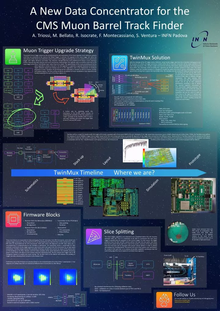
A New Data Concentrator for the CMS Muon Barrel Track Finder A. Triossi , M. Bellato , R. Isocrate , F. Montecassiano , S. Ventura – INFN Padova. Level Translator. De- mux. Virtex 7 XC7VX330T. GTH. GTH. Transmitter. Receiver. Snap12. Receiver. SelectIO. CML to LVDS.

E N D
A New Data Concentrator for the CMS MuonBarrel Track Finder A. Triossi, M. Bellato, R. Isocrate, F. Montecassiano, S. Ventura – INFN Padova Level Translator De-mux Virtex 7 XC7VX330T GTH GTH Transmitter Receiver Snap12 Receiver SelectIO CML to LVDS MiniPod Muon Trigger Upgrade Strategy The present muontrigger preserves the complementarity and redundancy of the three separate muon detection systems until they are combined at the input to the Global Trigger. In contrast, the upgrade to the muon trigger will utilize the redundancy of the three muon detection systems earlier in the trigger processing chain so as to obtain a more performant trigger with higher efficiency and better rate reduction. Recognizing that every additional hit along a muon trajectory further improves the fake rejection and muon momentum measurement, the upgrade seeks to combine muon hits at the input stage to the MuonTrack-Finder layer rather than at its output. The segmentation of the track processing will still be done regionally in sectors of φ and η. For the upgrade it is expected a separate treatment of transition region between barrel and endcap (|η|~1) in the algorithms and in the deployment of hardware processors as well. Therefore the processing will be subdivided in azimuth as well as in barrel, overlap, and endcap regions. The final sorting and ghost cancellation of muon candidates is also expected to be handled separately for each of the three regions in η TwinMux Solution With the redesign of the DT trigger Sector Collectors, which handle trigger data from the 4 chambers belonging to each 30° φ sector of a wheel, all trigger primitives created within the DT chamber minicrates will be made available to the track finder processors. This, besides a slight improvement of θhits information, allows skipping the sorting presently done within the minicrates while providing four segments per BX per chamber (instead of two). Each new Sector Collector, called the TwinMux because it is designed to handle the inputs from two DT sectors, will merge the 32 direct optical links coming from a sector into two 8 Gb/s links. The twinMux can also accept RPC data and hence can be used for receiving one DT and one RPC sector. In such case the total output corresponds to three 8 Gb/s links. In addition, through duplication, the data coming from each sector can also be synchronously fanned out to up to two additional destinations, providing a way to deliver the required neighbour information to each track-finder regional processor. This upstream duplication avoids the need of interconnections between processors. The duplication will also be used as a path to share data to the region of overlap with the endcap. Such new interconnection will replace the current coupling among the respective track-finders Barrel 0.8 η Overlap 1.2 η CSC DT RPC MPC SC LB Endcap CSCTF DTTF PAC CSC sorter DT sorter RPC sorter • One DT sector corresponds 32 LVDS lanes • One RPC sector correspond to max 5 GOL links • Each sector routed at most to 4 destinations (2 barrel and 2 overlap TPs) • DT bandwidth to TP: 2x8Gbps • RPC bandwidth to TP: 1x8Gbps GMT Vadatech VT892 JSM Power TwinMux TwinMux TwinMux TwinMux TwinMux TwinMux TwinMux TwinMux TwinMux TwinMux TwinMux AMC13 • CMS µTCA crate • Dual star backplane • 60 double-width and full-heightcards in 6 crates • Fabric A-B, Fabric D-G • FCLKA, TCLKA, TCLKB • Slow control • IPBUS, PCIEx, IPMI, JTAG • AMC13 commands • Connection to central DAQ for data spying A further way for exploiting earlier the redundancy of the DT-RPC system consists in combining the primitive of the two systems in a “super” primitive at the TwinMux level. In such a case each TwinMux will receive the trigger data of one DT and one RPC sector. CPU Power MCH1 CSC RPC DT MPC mezzanine LB CuOFOFCu LB CuOFOFCu Splitter Concent. TwinMux Splitter. Endcap TF & sorter Overlap TF & sorter Barrel TF & sorter Overlap TF & sorter TwinMux TwinMux will be a single slot double-width full-height μTCA board, equipped with 6 front panel SNAP12 RX and 2 Minipods TX for high speed data transmission (up to 13Gb/s). Based around a Xilinx Virex-7 FPGA, the TwinMux must achieve the merging of several 480Mb/s trigger links to higher speed serial links and compensate delays to provide BX alignment of the trigger data coming from the different inputs. Twelve of the 72 TwinMux inputs will be routable to GTH inputs to be able to handle the GOL based 1.6 Gb/s links. The expected latency is around 8 BX in total (2 BX for the deserialization, 5 BX for the output serialization and 2 BX to perform local operations, if preprocessing is not needed). Such latency is compatible with the TSC + OptoRX boards it will replace. To cover the full barrel, 60 TwinMux will be hosted in 6 μTCAcrates, each of which equippedwith an AMC13 GMT 8 LVDS @ 480 Mbps Trigger Processors SB 80 bit/BX each SB SB 4 Server Boards (2+1)x8 Gbps SB MBTF Twin Mux SB … 32 MBTF Prototype … LBM Stack-up 5 MOTF Layout LBM 480 bit/BX 5 Link Boards Master LBM MOTF LBM 32 bit/BX each LBM 1 GOL @ 1.6 Gbps LBM TwinMux Timeline Where we are? Top Ground GTH_1 Simulation Schematics Ground GTH_2 Ground Power Power Power Split_1 Power Split_2 Ground Bottom Firmware Blocks • Receiver from the Minicrates (480Mb/s) • Deserializer • BX alignment • Receiver from the LBs (1.6Gbps) • Deserializer • BX alignment • Uncompressing • Transmitter to the TP (8 Gb/s) • Data packing • Serializer • Slow control • TTC commands • PCIex IP/IPbus • DAQ link Soldermask removed from one PCB (scrap of production). We made sure that PCBs were manufactured at 22 degrees relative to the wave of the dielectric material in order not to be parallel to high speed lanes Slice Splitting The muon trigger upgrade is not expected to be completed before the LHC resumes operation after LS1. Thus it is imperative to be able to commission the new muon trigger in parallel with the operation of the current trigger. For that reason, the trigger primitives from the CSC and RPC systems will be fully split into two paths, and those from the DT system will be split from a slice of the system. A portion of the links coming from the minicrates will be equipped with passive optical splitters in order to deploy and validate the TwinMux board. The portion will cover three sectors over two wheels, for a total of 192 split links, so to enclose all possible neighbourcorrelations that the track finding algorithm has to explore to correlate track segments Three main blocks are responsible for data exchanging: from DT minicrates, from RPC link boards, and to barrel and overlap trigger processors. The data links from DT are deserialized by the SelectIO block of the standard pins, while RPC links are deserialized by the GTH transceivers. Both links need a BX alignment and RPC data needs also a uncompressing if a preprocessing on the TwinMux is performed. The transmitter blocks is responsible for data packing in accordance to the trigger processor data frame and it will exploit the GTH transceiver for an high speed serialization. TwinMux design foresee the possibility of having a double slow control: by means of PCI express lane on the backplane or by IPbus. Besides usual link status (unlocks, parity, signal detection), the available processing power in the FPGA’s will allow to host several improved monitoring tools, like for instance live trigger rate vs BX histograms layered on quality and muon sorting. The 10 Gb/s links to the AMC13 will enhance the probing of trigger raw data, allowing direct inclusion in the readout chain UXC USC From CuOF To SC To TwinMux Minicrate CuOF OFCu Sector Collector DTTF Follow Us You can get updates on TwinMux developing and debugging here: https://cern.ch/CMS-TM7 https://cern.ch/TwinMux Preliminary test of the firmware are already started on the characterization kit of the Virtex 7 speed grade -3. Eye diagrams of a 10Gb/s data links are collected at different level of clock jitter (0, 200, 500 ps) TwinMux MBTF Optical Splitter • No schedule interference for achieving validation tests • 2015 – validation on a slice: 6 sectors (bottom part of YB-2 and YB-1) • 2016 – full deployment • SelectIO in V7 speed grade -3 can de-serialize GOL links • Serializing /deserializing at 1.6Gbps in DDR • + 8/10b coding/decoding • Only BUFIO can run up to 800 MHz • Tested in external loopback with a 32bit counter BUFIO MMCM I S E R D E S 800MHz 40MHz IBUFGDS ÷5 BUFR