Download
1 / 14
170 likes | 683 Views
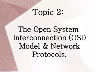
The International Standards Organization Reference Model of Open System Interconnection (ISO OSI model). Host A. Host B. 1. Application. Message. interfaces. 2. Presentation. Message. interfaces. 3. Session. Message. Subnet. 4. Transport. Message. Boundary. 5. Network. Packet.

E N D
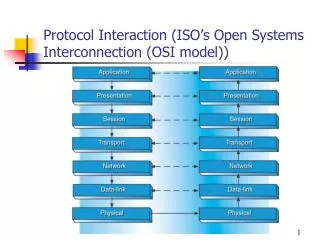
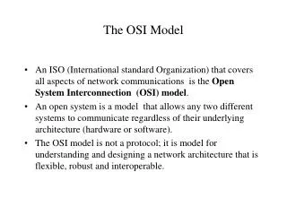
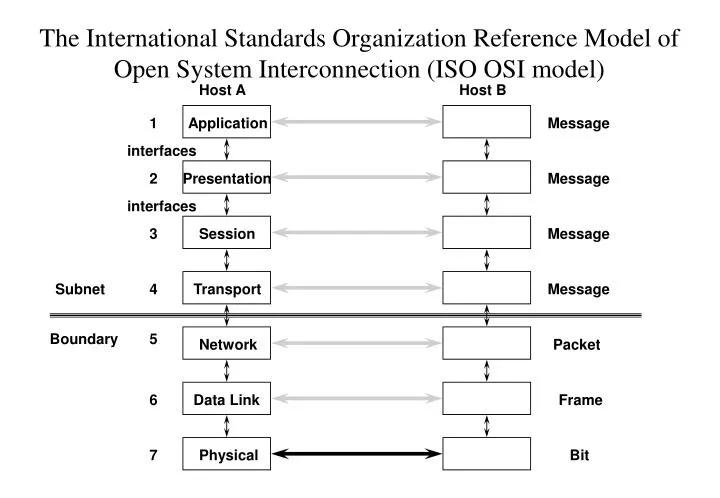
The International Standards Organization Reference Model of Open System Interconnection (ISO OSI model) Host A Host B 1 Application Message interfaces 2 Presentation Message interfaces 3 Session Message Subnet 4 Transport Message Boundary 5 Network Packet 6 Data Link Frame 7 Physical Bit
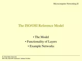
ISO OSI Model (The 7 Layers) Physical Layer specifies physical signals (electrical, optical), cabling/wiring. Data Link Layer frame boundaries, error detection (noise), flow control Network Layer how packets are sent from sources to destinations: routing, congestion control, inter-networking. Transport Layer break messages into packets, multiplex/demultiplex messages,end-to-end reliability. Session Layer provides users interface: directory, access rights, synchronization. Presentation Layer data encryption, data compression, code conversion. Application Layer virtual terminal, virtual file transfer
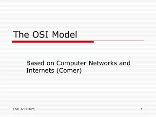
Information Transfer Application layer Message Presentation Session Transport Conversion layer Converted Message Packet layer Pkt Hdr First Pkt Pkt Hdr Second Pkt Frame layer Frame Hdr Pkt Hdr First Pkt Frame Hdr Pkt Hdr Second Pkt Physical layer Frames sent out onto network Implementation of Layering
Common Network Protocols • Ethernet (IEEE 802.3) 10Mbps • Carrier Sense Multiple Access / Collision Detect • Token-Bus (IEEE 802.4) • Physically a bus, logically a ring, token passing • Token-Ring (IEEE 802.5) 4-16Mbps • Ring topology, token passing • Slotted Aloha • Time slot, boardcasting • Slotted-ring (Cambridge ring) • Time multiplexing • Fibre Distributed Data Interface (FDDI) • High speed (100Mbps), token-bus like protocol • Integrated Service Digital Network (ISDN) • Multiples of 64kbps, up to 2 Mbps per channel for voice & video • ATM Switch (155 Mbps, 622Mbps) • Fast Ethernet (100Mbps), Giga-bit Ethernet (1Gbps)
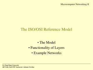
Network Card Popular protocols for PC DoD Netware/Novell IBM 7 - Application 6 - Presentation 5 - Session 4 - Transport 3 - Network 2 - Data Link 1 - Physical TCP SPX UDP NetBIOS IP IPX UDP:User Datagram Protocol TCP:Transmission Control Protocol IP:Internet Protocol SPX:Sequenced Packet eXchange IPX:Internetwork Packet eXchange
The Client-Server Model • A server is a program that provide a service. • It makes some resource available to other programs running somewhere on the network. • The resource could be anything: a database, a file system, a printer, a modem, a screen, or a scanner. • The server program runs on the machine which resource is attached to, and waits passively until the services are required. • Servers are often started up at boot-time, via commands in a start-up script and Servers usually spent most of their time asleep, waiting for work. • A client is a program that uses a resource. • It may be running on the machine to which the resource is attached, or on a different machine. • A client actively makes a connection across the network to the server it requires.
The Client-Server Model (continue) • The terms client and server are sometimes used to refer to a machine. • We may point out a computer on our network which has a large disk attached and say “That is our file server, and these workstations here are its clients”. • We may refer to a machine with a printer attached as a “print server”. • The term client and server refer to the relationship between individual programs, not to machines. • In general, machines cannot simply be labeled as clients and servers. • One machine might be a server for a piece of the file system, but a client of a remote print server. • Example, a program which is a server for a database might itself contact a time server to obtain an accurate timestamp to attach to a new record in the database. • In UNIX world, the term daemon is sometimes used to refer to a server. • It means that the server is “permanently available”, which implies that it is started at boot-time. • Daemon usually provide a “system-related” service, such as: rlogind, telnetd, ftpd, httpd, nfsd,… etc.
Client-Server Addressing • Machine.process / Machine.local-id addressing • Process addressing with broadcasting • Address lookup via a name-server. 1 3 C S C S 2 4 1 2 Hardwire machine.number into client code 1: Request to 234.0 2: Reply to 199.0 Processes pick a random #, locate them by broadcasting 1: Broadcast 2: Here I am 3: Request 4: Reply 3 1 Put ASCII server names in clients, look them up at run time 1: Look-up 2: NS reply 3: Request 4: Reply S C NS 4 2
Blocking versus Nonblocking Primitives • Blocking / Synchronous primitives • Nonblocking / Asynchronous primitives • 3 choices: • Blocking send (CPU idle during message transmission) • Nonblocking send with copy (CPU time wasted for the extra copy) • Nonblocking send with interrupt (make programming difficult) Client running Client running Client blocked Return from kernel, process released Trap to, kernel, process blocked message being sent Client running Client running Return Trap message being sent message copied to kernel buffer
Buffered versus Unbuffered Primitives Address refers to a mailbox Address refers to a process Client Server Client Server S C C S A A Kernel Kernel Reliable versus Unreliable Primitives 1 1 Client Server Client Server 3 2 4 2 3 1. Request (client to server) 2. ACK (kernel to kernel) 3. Reply (server to client) 4. ACK (kernel to kernel) 1. Request (client to server) 2. Reply (server to client) 3. ACK (kernel to kernel)
Remote Procedure Calls • The procedure call (same as function call or subroutine call) is a well-known method for transferring control from one part of a process to another, with a return of control to the caller. • Associated with the procedure call is the passing of arguments from the caller (the client) to the callee (the server). • In most current systems the caller and the callee are within a single process on a given host system. This is what we called “local procedure calls”. • In a remote procedure call (RPC), a process on the local system invokes a procedure on a remote system. The reason we call this a “procedure call” is because the intent is to make it appear to the programmer that a normal procedure call is taking place. • We use the term “request” to refer to the client calling the remote procedure, and the term “response” to describe the remote procedure returning its result to the client. • We will use the SUN RPC as our remote procedure call example. However, our example works for BSD as well with very minor modifications. • But let’s look at the steps that is involved in a remote procedure call.
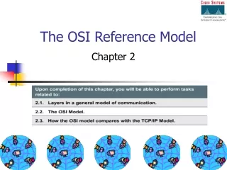
Client Process Server Process Client Server routines routines local procedure (10) (6) (5) call = (1) Client Server stub stub system call = (2) (9) (7) (4) (8) Network Network routines routines (3) = network communication local kernel remote kernel The 10 steps in a Remote Procedure Call (RPC)
The 10 steps in a Remote Procedure Call (continue) 1. The client calls a local procedure, called the client stub. It appears to the client that the client stub is the actual server procedure that it wants to call. The purpose of the stub is to package the arguments for the remote procedure, possibly put them into some standard format and then build one or more network messages. The packaging of the client's arguments into a network message is termed marshaling. 2. These network messages are sent to the remote system by the client stub. This requires a system call to the local kernel. 3. The network messages are transferred to the remote system. Either a connection-oriented or a connection-less protocol is used. 4. A server stub procedure is waiting on the remote system for the client's request. It unmarshals the arguments from the network message and possibly converts them. 5. The server stub executes a local procedure call to invoke the actual server function, passing it the arguments that it received in the network messages from the client stub. 6. When the server procedure is finished, it returns to the server stub with return values. 7. The server stub converts the return values, if necessary, and marshals them into one or more network messages to send back to the client stub. 8. The messages get transferred back across the network to the client stub. 9. The client stub reads the network messages from the local kernel. 10.After possibly converting the return values, the client stub finally returns to the client function. This appears to be a normal procedure return to the client.
Client-Server Application using RPC server procedure server program remote_server.c gcc remote_server server stub rpcgen remote_svc.c RPC specification file RPC run-time Library remote.x remote.h remote_clnt.c client procedure client stub client program remote_users.c gcc remote_users Please refer to “RPCNotes.doc” for the steps to write RPC Program on our linux platform (e.g. cslinux1)