Download
1 / 24
250 likes | 382 Views
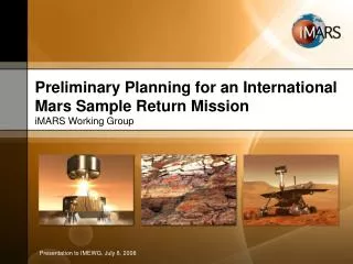
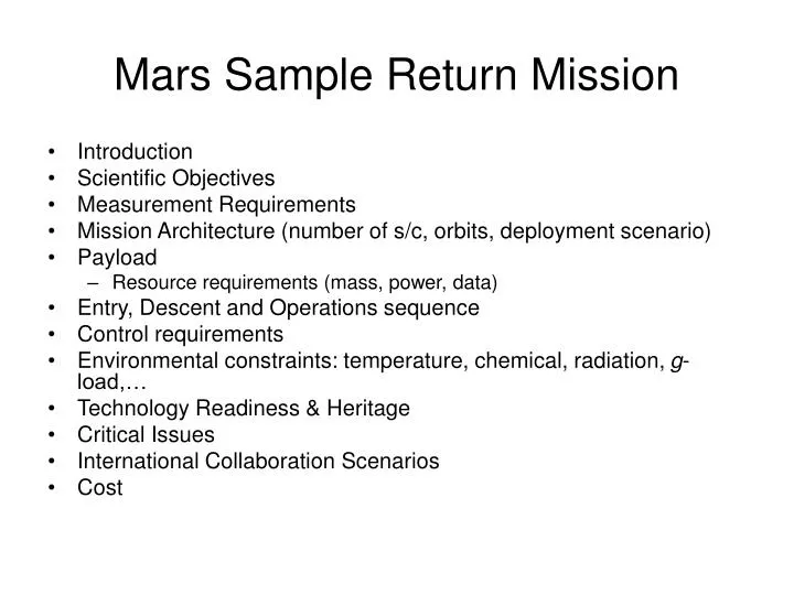
Mars Sample Return Mission. Introduction Scientific Objectives Measurement Requirements Mission Architecture (number of s/c, orbits, deployment scenario) Payload Resource requirements (mass, power, data) Entry, Descent and Operations sequence Control requirements

E N D
Mars Sample Return Mission • Introduction • Scientific Objectives • Measurement Requirements • Mission Architecture (number of s/c, orbits, deployment scenario) • Payload • Resource requirements (mass, power, data) • Entry, Descent and Operations sequence • Control requirements • Environmental constraints: temperature, chemical, radiation, g-load,… • Technology Readiness & Heritage • Critical Issues • International Collaboration Scenarios • Cost
Introduction • Mars Sample Return is key to Mars exploration • Returning a sample from Mars is very challenging (technical and cost) • Benefits come from existing orbiting and landed assets/experience (MRO, MSO, MSL) • Architecture includes orbiter, lander and ascent vehicle. • Requires precision landing to retrieve samples from MSL site. • Assumes samples are deposited into ascent vehicle by existing rover and placed in 400 km orbit for acquisition and return by orbiter
Science Objectives & Measurements • Objectives • Sample Return of 1kg from Mars • Drill cores • Sedimentary material • Long term surface meteorological measurements • Measurements • Sample context images • Meteorological data – temp, press,etc.
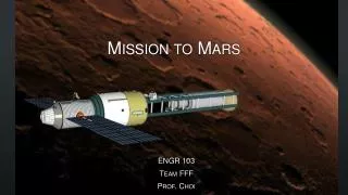
Mission Architecture • Orbiter(s) • Aerocapture orbit insertion • 400 km circular orbit • Lander • Type 2 trajectory with direct entry • Aero guidance, parachute, propulsive landing • Ascent Vehicle • Propulsive ascent to 400 km orbit – 2 units
Architecture Trades • Landing Accuracy: • Pinpoint <1km or 10 km • Mobility: • MSL or small MSR rover • Sample Transfer mechanism • On lander or rover • Landing site • Equatorial vs: mid-lattitude (TBD MSL Cache)
Payload • MET Station • PanCam • Ascent Vehicles (2) • Sample Transfer Mechanism
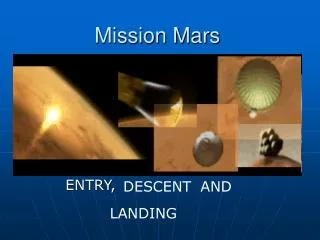
Entry Conditions • Lander targeted and released by orbiter prior to MOI via aerocapture • MSL style GN&C • MSO Nav. Assistance & Communication • Aerocapture by orbiter
Descent Phase • Release Backshell • Deploy Parachute at 2 km altitude • Release Lander at 300m altitude • Propulsive Landing
Parachute Design • Design • β<80kg/m2 • Subsonic parachute: Ring Sail • Deploy as late as possible • Release lander • Terminal velocity = 30 mps
Assumptions for landing phase • Requirements • Hazard avoidance (slope, rocks) • Soft landing (stable platform for ascent vehicle) <2m/s • Allocated landing accuracy with 1km • Landing mass 1000kg • Terminal velocity TBD to be optimised with the parachute system • Landing initiation TBD above ground • Environment: day only, rocks size 0.5m, local slope 20°, large scale slope 2° • Allocated mass & budgets TBD
Trades architectures • Trade • Sequence: TBD • Relative motion wrt terrain and hazard avoidance: Optical camera or LIDAR based • Actuators: liquid propulsion (pulsed, throttle..) • Final energy dissipation: airbags, legs, crushable structures, skycrane
Baseline: GNC sensors • LIDAR : for hazard avoidance (more robust to dust, glint, terrain illumination wrt camera) • IMU+LIDAR for vehicle state and relative motion with regard to terrain LIDAR
Baseline: Actuators • Propulsion : Hydrazine throttle engines (MSL like)
Baseline: Touchdown • Legs with capability to compensate for local slope: provide stable platform for ascent vehicle
Environmental Constraints • Assumed Mars Environment models • Low radiation
Technology Inherited • MSL • Guided aero entry • Thrusters • Subsystems • Parachutes • MER • Solar power • Aerocapture for orbiter not yet demonstrated at Mars
Critical Issues • Back planetary protection • Relies on MSL for sample cache • Relies on rendezvous sample transfer in Mars orbit using follow-on mission
International Collaboration • Orbiter • Ascent Vehicles • Sample Transfer HW • Follow-on capture mission
Cost • Flagship Class • Heavy use of heritage equipment from previous Mars missions