Download
1 / 38
390 likes | 496 Views
5.4 Circuit Analysis Using Phasors and Complex Impedances. Replace the time descriptions of the voltage and current sources with the corresponding phasors. (All of the sources must have the same frequency.).

E N D
5.4 Circuit Analysis Using Phasors and Complex Impedances • Replace the time descriptions of the voltage and current sources with the corresponding phasors. (All of the sources must have the same frequency.) 2. Replace inductances by their complex impedances ZL= jωL. Replace capacitances by their complex impedances ZC= 1/(jωC). Resistances have complex impedances equal to their resistances 3. Analyze the circuit using any of the techniques studied earlier in Chapter 2, performing the calculations with complex arithmetic.
Find the steady-state current for the circuit as follows, and also find the phasor voltage across each element and construct a phasor diagram. Answers:
Find the steady-state voltage uC(t) for the circuit as follows, and also find the phasor current through each element and construct a phasor diagram showing the currents and source voltage. Answers:
To find u1(t) in steady state. Answers:
To find i(t) in steady state; construct a phasor diagram showing all three voltages and current; what is the phasor relationship between us(t) and i(t)? Answers:
j200Ω -j50Ω • To find phasor voltage and the phasor current through each element in the circuit. Answers:
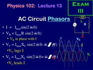
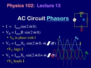
Steady-state Response of RLC in Series R Reactance
R • Steady-state Response of RLC in Series Voltage Triangle
R • Steady-state Response of RLC in Series Impedances Triangle
Power and Power Factor Power Factor 功率因数
Three Triangles S Q P R
Example 5.6: Computer the power and reactive power taken from the source and each element in the circuit. Answers:
Example 5.7:Find the power, reactive power and power factor for the source, find the phasor current i. Answers:
5.6 THÉVENIN EQUIVALENT CIRCUITS • The Thévenin voltage is equal to the open-circuit phasor voltage of the original circuit. • We can find the Thévenin equivalent impedance by zeroing the independent sources and determining the complex impedance looking into the circuit terminals.
5.6 THÉVENIN EQUIVALENT CIRCUITS The Thévenin impedance equals the open-circuit voltage divided by the short-circuit current.
Example 5.9: Find Thevenin equivalent circuit for the circuit. Answers:
Maximum Average Power Transfer • If the load can take on any complex value, maximum power transfer is attained for a load impedance equal to the complex conjugate of the Thévenin impedance. • If the load is required to be a pure resistance, maximum power transfer is attained for a load resistance equal to the magnitude of the Thévenin impedance.
Example 5.10: Determine the maximum power delivered to a load (a) the load can have any complex value; (b) the load must be a pure resistance. Answers:
5.7 BALANCED THREE-PHASE CIRCUITS • Much of the power used by business and industry is supplied by three-phase distribution systems. BALANCED THREE-PHASE CIRCUITS: Three equal-amplitude ac voltages have phases that are 1200 apart. Chapter 17 tells us how three-phase voltages are generated.
Wye (Y)-connected Line a、b、c 火线、相线 Neutral n 零线、中线 Positive phase sequence: a →b →c Phase voltage 相电压VY
Phase Sequence • Three-phase sources can have either a positive or negative phase sequence. • The direction of rotation of certain three-phase motors can be reversed by changing the phase sequence.
Wye–Wye Connection • Three-phase sources and loads can be connected either in a wye (Y) configuration or in a delta (Δ) configuration. • The key to understanding the various three-phase configurations is a careful examination of the wye–wye (Y-Y) circuit.
Balanced loads 对称负载 sources Line currents 线电流 Neutral currents 中线电流 Four-wire connection Balanced loads: All three load impedances are equal. • Under balanced three-phase sources and loads, Therefore, we can omit the neutral wire.
Wye–Wye Connection In a balanced three-phase system, neutral current is zero. we can eliminate the neutral wire. Then, compared with single phase circuit, only three wires are needed to connect the sources to the loads , it is less expensive.
Wye–Wye Connection Compared with single-phase circuit, the total instantaneous power in a balanced three-phase system is constant rather than pulsating. • Reactive power
(线电压) A(相电压) B(相电压)
A balanced positive-sequence wye-connected 60 Hz three-phase source has phase voltage UY=1000V. Each phase of the load consists of a 0.1-H inductance in series with a 50-Ω resistance. • Find the line currents, the line voltages, the power and the reactive power delivered to the load. Draw a phasor diagram showing line voltages, phase voltages and the line currents. Assuming that the phase angle of Uan is zero.
Delta (Δ)-connected Sources According to KVL, Thus, the current circulating in the delta is zero.
Wye (Y) and Delta (Δ)-connected Loads Two balanced loads are equal.
Delta - Delta (Δ- Δ) connection Line current Assuming line voltage Then, we get phase current
A delta-connected source supplies power to a delta-connected load through wires having impedances of Zline=0.3+j0.4Ω, the load impedance are ZΔ=30+j6 Ω, the balanced source A voltage is Find the line current, the line volatge at the load, the current in each phase of the load, the power delivered to the load, and dissipated in the line.
Homework 5 • P5.24 • P5.34 • P5.43 • P5.53 • P5.68 • P5.72