Download
1 / 13
160 likes | 382 Views
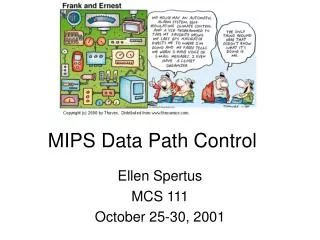
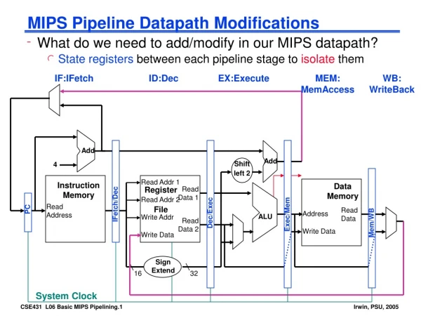
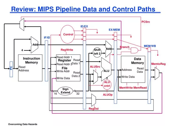
Review: MIPS Pipeline Data and Control Paths. PCSrc. ID/EX. EX/MEM. Control. IF/ID. Add. MEM/WB. Branch. Add. 4. RegWrite. Shift left 2. Read Addr 1. Instruction Memory. Data Memory. Register File. Read Data 1. Read Addr 2. MemtoReg. Read Address. ALUSrc. PC. Read

E N D
Review: MIPS Pipeline Data and Control Paths PCSrc ID/EX EX/MEM Control IF/ID Add MEM/WB Branch Add 4 RegWrite Shift left 2 Read Addr 1 Instruction Memory Data Memory Register File Read Data 1 Read Addr 2 MemtoReg Read Address ALUSrc PC Read Data Address Write Addr ALU Read Data 2 Write Data Write Data ALU cntrl MemWrite MemRead Sign Extend 16 32 ALUOp RegDst
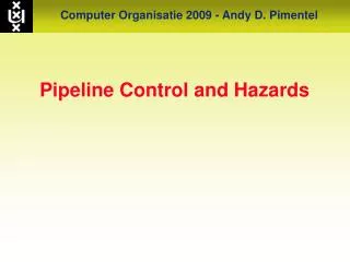
DM DM DM DM DM Reg Reg Reg Reg Reg Reg Reg Reg Reg Reg IM IM IM IM IM ALU ALU ALU ALU ALU Review: Another Way to “Fix” a Data Hazard Fix data hazards by forwarding results as soon as they are available to where they are needed add $1, I n s t r. O r d e r sub $4,$1,$5 and $6,$7,$1 or $8,$1,$1 sw $4,4($1)
Data Forwarding (aka Bypassing) • Take the result from the earliest point that it exists in any of the pipeline state registers and forward it to the functional units (e.g., the ALU) that need it that cycle • For ALU functional unit: the inputs can come from any pipeline register rather than just from ID/EX by • adding multiplexors to the inputs of the ALU • connecting the Rd write data in EX/MEM or MEM/WB to either (or both) of the EX’s stage Rs and Rt ALU mux inputs • adding the proper control hardware to control the new muxes
Data Forwarding Control Conditions • EX/MEM hazard: if (EX/MEM.RegWrite and (EX/MEM.RegisterRd != 0) and (EX/MEM.RegisterRd = ID/EX.RegisterRs)) ForwardA = 10 if (EX/MEM.RegWrite and (EX/MEM.RegisterRd != 0) and (EX/MEM.RegisterRd = ID/EX.RegisterRt)) ForwardB = 10 Forwards the result from the previous instr. to either input of the ALU MEM/WB hazard: if (MEM/WB.RegWrite and (MEM/WB.RegisterRd != 0) and (MEM/WB.RegisterRd = ID/EX.RegisterRs)) ForwardA = 01 if (MEM/WB.RegWrite and (MEM/WB.RegisterRd != 0) and (MEM/WB.RegisterRd = ID/EX.RegisterRt)) ForwardB = 01 Forwards the result from the second previous instr. to either input of the ALU
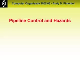
DM DM DM Reg Reg Reg Reg Reg Reg IM IM IM ALU ALU ALU Forwarding Illustration add $1, I n s t r. O r d e r sub $4,$1,$5 and $6,$7,$1 EX/MEM hazard forwarding MEM/WB hazard forwarding
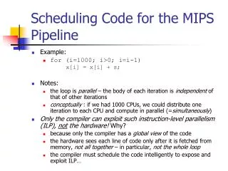
DM DM DM Reg Reg Reg Reg Reg Reg IM IM IM ALU ALU ALU Yet Another Complication! • Another potential data hazard can occur when there is a conflict between the result of the WB stage instruction and the MEM stage instruction – which should be forwarded? I n s t r. O r d e r add $1,$1,$2 add $1,$1,$3 add $1,$1,$4
Corrected Data Forwarding Control Conditions • MEM/WB hazard: if (MEM/WB.RegWrite and (MEM/WB.RegisterRd != 0) and (EX/MEM.RegisterRd != ID/EX.RegisterRs) and (MEM/WB.RegisterRd = ID/EX.RegisterRs)) ForwardA = 01 if (MEM/WB.RegWrite and (MEM/WB.RegisterRd != 0) and (EX/MEM.RegisterRd != ID/EX.RegisterRt) and (MEM/WB.RegisterRd = ID/EX.RegisterRt)) ForwardB = 01
ID/EX EX/MEM Control IF/ID Add MEM/WB Branch Add 4 Shift left 2 Read Addr 1 Instruction Memory Data Memory Register File Read Data 1 Read Addr 2 Read Address PC Read Data Address Write Addr ALU Read Data 2 Write Data Write Data ALU cntrl 16 32 Sign Extend EX/MEM.RegisterRd ID/EX.RegisterRt Forward Unit MEM/WB.RegisterRd ID/EX.RegisterRs Datapath with Forwarding Hardware PCSrc
DM DM Reg Reg Reg Reg IM IM ALU ALU Memory-to-Memory Copies • For loads immediately followed by stores (memory-to-memory copies) can avoid a stall by adding forwarding hardware from the MEM/WB register to the data memory input. • Would need to add a Forward Unit and a mux to the memory access stage I n s t r. O r d e r lw $1,4($2) sw $1,4($3)
DM DM DM DM DM Reg Reg Reg Reg Reg Reg Reg Reg Reg Reg stall IM IM IM IM IM IM ALU ALU ALU ALU ALU ALU and $6,$1,$7 and $6,$1,$7 or $8,$1,$9 or $8,$1,$9 xor $4,$1,$5 xor $4,$1,$5 DM Reg Forwarding with Load-use Data Hazards lw $1,4($2) I n s t r. O r d e r sub $4,$1,$5 sub $4,$1,$5
Load-use Hazard Detection Unit • Need a Hazard detection Unit in the ID stage that inserts a stall between the load and its use ID Hazard Detection if (ID/EX.MemRead and ((ID/EX.RegisterRt = IF/ID.RegisterRs) or (ID/EX.RegisterRt = IF/ID.RegisterRt))) stall the pipeline • The first line tests to see if the instruction now in the EX stage is a lw; the next two lines check to see if the destination register of the lw matches either source register of the instruction in the ID stage (the load-use instruction) • After this one cycle stall, the forwarding logic can handle the remaining data hazards
Stall Hardware • Along with the Hazard Unit, we have to implement the stall • Prevent the instructions in the IF and ID stages from progressing down the pipeline – done by preventing the PC register and the IF/ID pipeline register from changing • Hazard detection Unit controls the writing of the PC (PC.write) and IF/ID (IF/ID.write) registers • Insert a “bubble” between the lw instruction (in the EX stage) and the load-use instruction (in the ID stage) (i.e., insert a noop in the execution stream) • Set the control bits in the EX, MEM, and WB control fields of the ID/EX pipeline register to 0 (noop). The Hazard Unit controls the mux that chooses between the real control values and the 0’s. • Let the lw instruction and the instructions after it in the pipeline (before it in the code) proceed normally down the pipeline
ID/EX.MemRead 0 ID/EX.RegisterRt Adding the Hazard Hardware PCSrc Hazard Unit ID/EX EX/MEM 0 IF/ID 1 Control Add MEM/WB Branch Add 4 Shift left 2 Read Addr 1 Instruction Memory Data Memory Register File Read Data 1 Read Addr 2 Read Address PC Read Data Address Write Addr ALU Read Data 2 Write Data Write Data ALU cntrl 16 32 Sign Extend Forward Unit