Download

1 / 47
480 likes | 620 Views
Fluid and Deformable-Structure Interactions in Bio-Mechanical Systems. Lucy Zhang Department of Mechanical, Aerospace, and Nuclear Engineering Rensselaer Polytechnic Institute Troy, NY. Immersed Boundary Method (Peskin) - flexible solid immersed in fluid

E N D
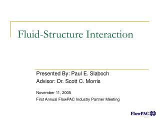
Fluid and Deformable-Structure Interactions in Bio-Mechanical Systems Lucy Zhang Department of Mechanical, Aerospace, and Nuclear EngineeringRensselaer Polytechnic Institute Troy, NY
Immersed Boundary Method (Peskin) - flexible solid immersed in fluid • structures are modeled with elastic fibers • finite difference fluid solver with uniform grid • Arbitrary Lagrangian Eulerian (ALE) • limited to small mesh deformations • requires frequent re-meshing or mesh update • Goals: • accurate (interpolations at the fluid-structure interface) • efficient (less/no mesh updating required) • flexible (deformable and rigid structures, boundary conditions) • extensibility (multi-phase flows, various applications)
solid solid t = t1 Finite element based approach for: Fluid-deformable structure interactions t=0 • Assumptions: • No-slip boundary condition at the fluid-solid interface • Solid is completely immersed in the fluid • Fluid is everywhere in the domain
Principle of virtual work: 3 2 1 1 2 3 s Equations of motion
Overlapping s fluid: in in s Solid:
solid node Influence domain Surrounding fluid nodes Uniform spacing Interpolations at the interface Force distribution Velocity interpolation
Algorithm Read solid & fluid Geometries Apply initial conditions Fluid analysis (N-S) Solve for vfluid Structure analysis Solve for FFSI,s Interpolate vfluid onto solids Vsolid vfluid->Vsolid Distribute F onto the fluid FFSI,s -> FFSI Update solids positions dsolid=Vsolid*dt
Soft disk falling in a channel Leaflet driven by fluid flow Flow past a cylinder 3 rigid spheres dropping in a channel Validations
A soft disk falling in a viscous fluid Particle (elastic): Density= 3,000 kg/m3 Young modulus: E = 1,000 N/m2 Poisson ratio: 0.3 Gravity: 9.81 m/s2 Particle mesh: 447 Nodes and 414 Elements Fluid: Tube diameter, D = 4d =2 cm Tube height, H = 10 cm Particle diameter, d = 0.5 cm Density= 1,000 kg/m3 Fluid viscosity = 0.1 N/s.m2 Fluid initially at rest Fluid mesh: 2121 Nodes and 2000 Elements
Stress distribution on the soft disk t = 0.0 s t = 1.1 s t = 2.2 s t = 3.3 s t = 4.35 s
Terminal velocity of the soft disk Comparison between the soft sphere and the analytical solution of a same-sized rigid sphere
Why is it unique? • fluid- deformable structure interactions • two-way coupling, higher order interpolation function • Limitations? • time step constraint • rigid solid case • Possible expansions? • compressible system • multiphase flow • Usefulness? • numerous applications! X. Wang - " An iterative matrix-free method in implicit immersed boundary/continuum methods, " Computers & Structures, 85, pp. 739-748, 2007.
Use numerical methods to understand and study cardiovascular diseases. • Find non-invasive means to predict physical behaviors and seek remedies for diseases • Simulate the responses of blood flow (pressure and velocities) under different physiologic conditions. • Compare our results (qualitatively) with published clinical data and analyze the results.
Biomechanical applications Heart modeling - left atrium Red Blood Cell aggregation Deployment of angioplasty stent Venous valves Large deformation (flexible)
Why heart? Cardiovascular diseases are one of the leading causes of death in the western world. Cardiovascular diseases (CVD) accounted for 38.0 percent of all deaths or 1 of every 2.6 deaths in the United States in 2002. It accounts for nearly 25% of the deaths in the word. In 2005 the estimated direct and indirect cost of CVD is $393.5 billion.
Cardiovascular system A: The oxygen-rich blood (red) from the pulmonary vein fills the left atrium. B: The oxygen-rich blood in the left atrium fills the left ventricle via the mitra valve. C: The left ventricle contracts and sends the oxygen-rich blood via aortic valve and aorta to the systemic circulation. F A D: The oxygen-poor blood (blue) from the superior vena cava and inferior vena cava fills the right atrium. E: The oxygen-poor blood in the right atrium fills the right ventricle via tricuspid valve. F: The right ventricle contracts and sends the oxygen-poor blood via pulmonary valve and pulmonary artery to the pulmonary circulation. C D B E
Left atrial appendage Without blood clots with a blood clot Atrial fibrillation and blood flow During Atrial Fibrillation (a particular form ofan irregular or abnormal heartbeat): The left atrium does not contract effectively and is not able to empty efficiently. Sluggishbloodflow may come inside the atrium. Bloodclots may form inside the atrium. Blood clots may breakup Result in embolism. Result in stroke.
Left atrium Pulmonary veins Pulmonary veins Pulmonary veins Pulmonary veins Mitral valve Left atrium Blood clots Left atrial appendage Left atrium geometry Courtesy of Dr. A. CRISTOFORETTI, ale@science.unitn.it University of Trento, Italia G. Nollo, A. Cristoforetti, L. Faes, A. Centonze, M. Del Greco, R. Antolini, F. Ravelli: 'Registration and Fusion of Segmented Left Atrium CT Images with CARTO Electrical Maps for the Ablative Treatment of Atrial Fibrillation', Computers in Cardiology 2004, volume 31, 345-348;
56mm 17mm 77mm 20mm 28mm Left atrium geometry From Schwartzman D., Lacomis J., and Wigginton W.G., Characterization of left atrium and distal pulmonary vein morphology using multidimensional computed tomography. Journal of the American College of Cardiology, 2003. 41(8): p. 1349-1357 Ernst G., et al., Morphology of the left atrial appendage. The Anatomical Record, 1995. 242: p. 553-561. Left atrium Left atrial appendage Pulmonary veins
Left atrium with pulmonary veins During diastole (relaxes, 0.06s < t < 0.43s) , no flow through the mitral valve (v=0) During systole (contracts, 0.43s < t < 1.06s), blood flow is allowed through the mitral valve (free flow) Blood is assumed to be Newtonian fluid, homogenous and incompressible. Maximum inlet velocity: 45 cm/s Blood density: 1055 kg/m3 Blood viscosity: 3.5X10⁻³ N/s.m2 Fluid mesh: 28,212Nodes, 163,662 Elements Solid mesh: 12,292 Nodes, 36,427 Elements Klein AL and Tajik AJ. Doppler assessment of pulmonary venous flow in healthy subjects and in patients with heart disease. Journal of the American Society of Echocardiography, 1991, Vol.4, pp.379-392.
Wall muscle constitutive equation Passive strain during diastole Strain energy Active strain during systole Green-Lagrange strain Second Piola-Kirchhoff stress First Piola-Kirchhoff stress From W. Xie and R. Perucchio, “Computational procedures for the mechanical modeling of trabeculated embryonic myocardium”, Bioengineering Conference, ASME 2001, BED-Vol. 50, pp. 133-134
Left atrium with appendage Transmitral velocity during diastole Pressure distribution at the center of the atrium during a diastole and systole cycle
Pressure (mm hg) 5 0 1 1.5 2 Time (s) Left atrium (comparison with clinical data) Kuecherer H.F., Muhiudeen I.A., Kusumoto F.M., Lee E., Moulinier L.E., Cahalan M.K. and Schiller N.B., Estimation of mean left atrial pressure from transesophageal pulsed Doppler echocardiography of pulmonary venous flow Circulation, 1990, Vol 82, 1127-1139 Pressure distribution at the center of the atrium during one cardiac cycle A E Transmitral velocity during one cardiac cycle
Influence of the appendage Transmitral velocity during one cardiac cycle (with and without the appendage) Velocity inside the appendage during one cardiac cycle
Red blood cells and blood FEM RBC model RBC empirical function From Dennis Kunkel at http://www.denniskunkel.com/ • Property of membrane • Thickness of RBC membrane: 7.5 to 10 nm • Density of blood in 45% of hematocrit: 1.07 g/ml • Dilation modulus: 500 dyn/cm • Shear modulus for RBC membrane: 4.2*10-3dyn/cm • Bending modulus: 1.8*10-12 dyn/cm. • Property of inner cytoplasm • Incompressible Newtonian fluid
Bulk aggregates Discrete cells Cell layers Red blood cells and blood The shear rate dependence of normal human blood viscoelasticity at 2 Hz and 22 °C (reproduced from http://www.vilastic.com/tech10.html)
Shear of a RBCs Aggregate RBC-RBC protein dynamic force is coupled with IFEM (NS Solver) The shear of 4 RBCs at low shear rate The RBCs rotates as a bulk The shear of 4 RBCs at high shear rate The RBCs are totally separated and arranged at parallel layers The shear of 4 RBCs at medium shear rate The RBCs are partially separated
-2 -4 -3 log (m) -6 -5 biomaterial -8 -7 Shear induced heart How to link all these together? vessel red blood cell platelet protein
Micro-air vehicles three types of MAVs: airplane-like fixed wing model, helicopter-like rotating wing model, bird-or insect-like flapping wing model. 10-4 10-3 10-2 10-1 1 10102 103 104 105 106 Gross Weight (Lbs) potential military and surveillance use http://www.fas.org/irp/program/collect/docs/image1.gif
muscle contraction Bio-inspired flapping wings
Acknowledgement • Graduate students: • Mickael Gay, Yili Gu • Collaborators: • Dr. Holger Salazar (Cardiology Department, Tulane University) • Dr. A. Cristoforetti (University of Trento, Italy) • Funding agencies: NSF, NIH, Louisiana BOR • Computing resources: • Center for Computational Sciences (CCS) - Tulane • SCOREC (RPI)
What can you do? Eat Healthy!
IFEM: Governing Equations Governing equation of structure Force distribution Navier-Stokes equation for incompressible fluid Velocity interpolation
Internal Forces: hyperelastic material description (Mooney-Rivlin material). S – 2nd Piola Kirchhoff stress tensor ε - Green Lagrangian strain tensor Total Lagrangian Formulation External Forces: External forces can be arbitrary forces from diverse force fields (e.g. gravity, buoyancy force, electro-magnetic fields). g– acceleration due to gravity IFEM: Solid Force Calculation
in in IFEM Governing Equations II. Insert this inhomogeneous fluid force field into the N-S eqn. Distribution of interaction force The interaction force fFSI,s is distributed to the fluid domain via RKPM delta function. I. III. Solve for velocity using the Navier-Stokes equation Eq. (III) The interaction force is calculated with Eq. (I) IV. P and v unknowns are solved by minimizing residual vectors (derived from their weak forms) Update solid displacement with solid velocity The fluid velocity is interpolated onto the solid domain via RKPM delta function
Bulk aggregates Discrete cells Cell layers Shear rate dependence of normal human blood viscoelasticity at 2 Hz and 22 °C (reproduced from http://www.vilastic.com/tech10.html) Red blood cell model RBC From Dennis Kunkel at http://www.denniskunkel.com/
Venous Valve Courtesy of H.F. Janssen, Texas Tech University. • Site of deep venous thrombosis formation • Prevents retrograde venous flow (reflux) • Site of sluggish blood flow • Decreased fibrinolytic activity • Muscle contraction prevents venous stasis: • Increases venous flow velocity • Compresses veins • Immobilization promotes venous stasis
Venous Valve Comparison between experiment and simulation at 4 different time steps
Multi-resolution analysis • Window function with a dilation parameter: a: dilation parameter • Projection operator for the scale a • Wavelet function: • Complementary projection operator: low scale + high scale