Download
1 / 15
160 likes | 279 Views
Lab 1: Logic Gate Systems :. Binary Number System:. Slide #2. Decimal Numbers:. Slide #3. Binary Number Conversion:. Slide #4. Switches and LED’s:. Slide #5. The NOT gate:. Slide #6. The OR gate:. Slide #7. The AND gate:. Slide #8. NOR Gate:. Slide #9. NAND Gate:. Slide #10.

E N D
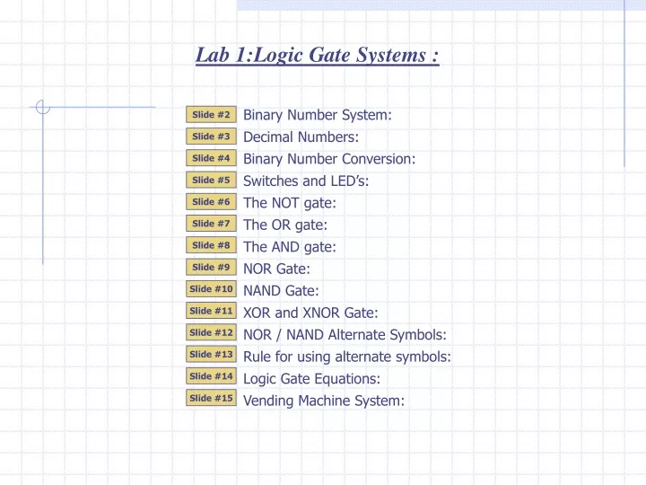
Lab 1:Logic Gate Systems : Binary Number System: Slide #2 Decimal Numbers: Slide #3 Binary Number Conversion: Slide #4 Switches and LED’s: Slide #5 The NOT gate: Slide #6 The OR gate: Slide #7 The AND gate: Slide #8 NOR Gate: Slide #9 NAND Gate: Slide #10 XOR and XNOR Gate: Slide #11 NOR / NAND Alternate Symbols: Slide #12 Rule for using alternate symbols: Slide #13 Logic Gate Equations: Slide #14 Vending Machine System: Slide #15
Driver Viewing Window 9 9 9 0 0 0 1 0 1 1 1 0 0 0 0 1 0 0 0 0 1 0 Lab 1 : Binary Number System: We will use a car odometer to learn about the binary number system. A car odometer (non-digital) consists of a series of plastic discs that rotate to track the distance traveled by a car. A decimal odometer has the outer edge of each disc numbered from 0 … 9. Three discs will allow the odometer to record a maximum distance traveled of 999 Km’s. A binary odometer has the outer edge of each disc numbered with only 0 and 1. Using 3 discs will allow the odometer to record a maximum distance traveled of 111 binary Km’s … or … 7 km’s. Proceed to watch the odometer in action. 1 1 1 1 3 Bit Binary From the odometer example, you can place the 3 bit numbers in a table and see the order of the first 8 binary numbers. Slide #2
Hundreds Thousands Tens One’s 10-2 100 101 102 103 10-1 5 one’s 3 tens 2 Hundreds Lab 1 : Decimal Numbers : Reviewing some fundamental facts about the decimal number system will help you learn the binary number system. The decimal positional weight chart (PWC). Each numeral of a decimal number occupies a position that has a weight. Here is the decimal PWC. 2 3 5 The weight of each position have been given names. A decimal point is used to separate the whole part and the fractional part of a number. Here is the decimal number 235 placed in the PWC. Slide #3
4 20 21 22 23 1 2 2 8 32 16 8 4 1 1 1 0 1 Lab 1 : Binary Number Conversions : Digital systems process data in binary format. It is important to know how to convert back and forth from binary to decimal. Binary numbers are part of a base 2 number system. Only two numerals exist: 1 and 0. Converting binary to decimal: Drop the binary number into the binary PWC to convert it to decimal. Example convert 11012 to decimal. … Or … Binary PWC = 1x8 + 1x4 + 0x2 + 1x1 = 8+4+0+1 = 1310 Converting decimal to binary: Example: convert 2510 to binary Write down a binary PWC which the MSB (most significant bit) surpasses the number you are trying to convert. Work from MSB and use a 1 to include the bit position and a 0 to exclude it. The included bits should have their weight add up to the number being converted. Exclude because 16 + 8 + 2 will exceed 25. Include because 16 + 8 + 1 will equal 25. Include because 16 + 8 does not exceed 25. Exclude because 16 + 8 + 4 will exceed 25. Include because 16 does not exceed 25. Exclude because it would make number larger than 25 0 1 1 0 0 1 Slide #4
5v ON ON OFF OFF OFF ON 5v Logic 1 Logic 1 Logic 1 Input Output Logic 0 Logic 0 Logic 0 Digital System Lab 1 : Switches and LED’s: Students can create and test digital systems by using switches to represent binary input data and using LED’s (light emitting diode) to represent binary output data. Digital systems have an input side and an output side. Each arrow is a connection wire. The inputs of a digital system are binary digits (bits). You either input a binary 1 (logic 1) or a binary 0 (logic 0). The digital system processes the signals you have applied to the input and responds with binary 1 or binary 0 at the output(s). 5 volts represents a logic 1 and a 0 volts (also called GROUND or Gnd) represents a logic 0. The digital system is powered up by a 5 Volt power supply. A switch can be used to input a logic 1 and logic 0. An LED can be connected to the output to see the digital system’s response. Continue and you will see the switch and LED in action. Slide #5
OFF OFF OFF ON ON ON 5v Input A Output X Logic 1 Logic 1 Logic 1 Logic 0 Logic 0 Logic 0 Lab 1:The NOT Gate (inverter): The NOT gate is the first of the three fundamental logic gates. You will learn its operation using Truth Table analysis and an animation. Truth Table: Is a chart that lists the input condition on the left and the gate’s output response on the right. The table shows that the NOT gate responds at the output with the inverse of the signal applied to the input. Animation: In order to see how it works, the gate has been connected to a switch and LED. Continue to see the system in action… Slide #6
Logic 1 Logic 1 Logic 0 Logic 1 Logic 1 OR 5v Input A Output X Input B Logic 1 Logic 0 5v Logic 0 Logic 1 Logic 1 5v Logic 0 Logic 0 Lab 1: The OR Gate: The OR gate is the second of three fundamental logic gates. You will learn its behaviour using a Truth Table analysis and an animation. Truth Table: The table shows that the OR gate responds with a high at the output if the signal applied to the input A or B is high. Animation: In order to see how it works, the gate has been connected to 2 switches and LED. Continue to see the system in action… Slide #7
Logic 1 Logic 1 Logic 1 5v Logic 1 Logic 0 AND Logic 0 Logic 0 5v Input A Output X Logic 0 Logic 0 Input B 5v Logic 0 Logic 1 Logic 0 Lab 1: The AND Gate: The AND is the last of the remaining fundamental logic gates. You will learn its behaviour using a Truth Table analysis and an animation. Truth Table: The table shows that the AND gate responds with a high at the output if the signal applied to the input A and B are both high. Animation: In order to see how it works, the gate has been connected to 2 switches and LED. Continue to see the system in action… Slide #8
Logic 1 Logic 1 Logic 0 Logic 0 Logic 0 Logic 0 Logic 0 Logic 1 5v NOR Logic 0 5v Input A Logic 1 Output X Logic 1 Logic 0 Input B 5v Lab 1 : NOR Gate The NOR gate is equivalent to an OR gate with a NOT gate connected to its output. NOR comes from the words Not OR. Continue to see the standard symbol for NOR. NOR Symbol Truth Table: The table shows that the NOR gate responds with a low at the output if the signal applied to the input A or B is high. System animation: In order to see how it works, the gate has been connected to 2 switches and LED. Continue to see the system in action… Boolean Equation: here is the equation for the NOR gate. Slide #9
Logic 1 Logic 1 Logic 0 Logic 0 Logic 0 Logic 1 Logic 1 5v Logic 1 NAND 5v Input A Logic 1 Logic 0 Output X Logic 0 Logic 1 Input B 5v Lab 1 : NAND Gate The NAND gate is equivalent to an AND gate with a NOT gate connected to its output. NAND comes from the words Not AND. Continue to see the standard symbol for NAND. NAND Symbol Truth Table: The table shows that the NAND gate responds with a low at the output if the signal applied to the input A and B is high. System animation: In order to see how it works, the gate has been connected to 2 switches and LED. Continue to see the system in action… Boolean Equation: here is the equation for the NAND gate. Slide #10
XOR XNOR Input A Input A Output X Output X Input B Input B Lab 1 : XOR Gate The XOR gate is an exclusive OR gate. It will output a logic 1 if there is an exclusive logic 1 at input A or B. Exclusive means: Only one input can be high at one time. Truth Table: The table shows that the XOR gate responds with a high at the output if the signal applied to the input A or B is high (but not both high). XOR Boolean Equation: The XNOR gate is an exclusive OR gate with an NOT gate at the output. It will output a logic 0 if there is an exclusive logic 1 at input A or B. XOR Boolean Equation: Slide #11
NOT NOR NAND 0 OR 0 = 1 0 AND 0 = 1 Alternate NOR Alternate NAND Lab 1 : NOR and NAND Gate Alternate Symbols: The NAND and NOR logic gate symbols you have studied are called the “standard” symbols. Each gate also has an “alternate” symbol. The “standard” logic symbols for the NAND and NOR gates indicates a gates response to “logic 1” at the input. Alternate NOR GATE: The bubbles at the input of the NOR gate implies that a “logic 0” at input A and a “logic 0” at input B are required to produce a “logic 1” at output X (NO bubble at output). Alternate NAND GATE: The bubbles at the input of the NAND gate implies that a “logic 0” at input A or a “logic 0” at input B are required to produce a “logic 1” at output X (NO bubble at output). Slide #12
= = = 5V Active High LED Active Low LED A logic 1 lights the LED 1 A logic 0 lights the LED 0 Lab 1 :Rule for Using the Alternate symbols : The basic logic gates AND, OR, and NOT have standard logic symbols and alternate logic symbols. A general rule for using alternate symbols exists. The rule is a guide and not a strict rule. Some designers do not use the rule but many do. Standard Alternate The rule is simple : Active high device connects to active high symbol : Active low device connects to the active low symbol. Example: Connect an LED to an AND gate: There are two types of LED connections. Active high device connects to active high symbol (standard).Active low device connects to the active low symbol (alternate). Slide #13
NOT Boolean Equation: Boolean Equation: Boolean Equation: OR Input A Input A Input A Output X Output X Output X Input B Boolean Equation: AND Input A Output X Input B Lab 1 : Logic Gate Equations: Each logic gate has a Boolean equation to represent its operation. Slide #14
1 Q3 1 1 1 1 Q2 P 0 1 0 Q1 C 0 L 1 1 C2 1 0 0 0 0 0 1 0 0 1 0 0 0 0 1 0 0 0 1 0 1 0 1 1 0 1 1 1 Lab 1 : Vending Machine System: Design a logic system for a vending machine that will dispense a 75 cent surprise gift package if any of the following conditions occur… Three quarters are inserted. A dollar is inserted. The machine can only accept quarters and a dollar coin / note. Step 1: Declare Inputs and Outputs: Inputs : Quarters (Q1, Q2, Q3). Dollar (L). Logic 1 = currency present. Outputs : Package (P). Quarter Change (C). Logic 1 = dispense item. Q1 • Q2• Q3 = + L L Step 2: Generate Equation for the system: Dispense Package if Quarter1 and Quarter2 and Quarter3 OR Dollar is inserted. Dispense change if dollar is inserted. P = Q1 • Q2• Q3 + L C = L Once the system diagram is complete it can be used to test the operation of the system. Here is what happens when someone inserts 3 quarters. Here is what happens when someone inserts a dollar. P-Term : thus : P = + L Here is what happens when someone searches their pocket finds a quarter and inserts it into the machine. Then they realize that they do not have 2 more quarters! If they insert a dollar what would be the result? Step 3: Draw the Digital System Diagram : Group variables that are ANDed together into a single block. This block is called product term (P-Term). The result: The package and the change would be dispensed. The un-happy user of the machine would have paid $1 ($1.25 - $0.25 change). To resolve this problem an extra change output could be added. Work from output towards input. P must be connected to an OR gate. Slide #15 Re-insert the P-Term (Q1 • Q2• Q3). A 3 input AND gate is required. Connect L to OR gate and connect C to L (C=L).