Download
1 / 48
500 likes | 713 Views
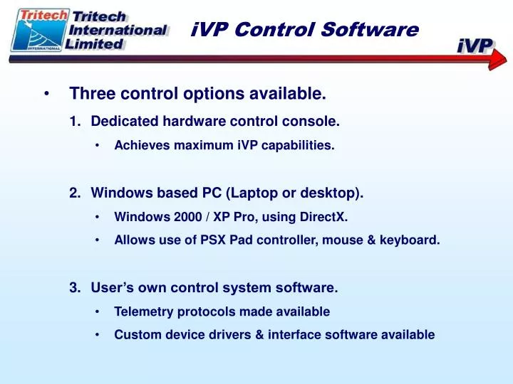
iVP Control Software. Three control options available. Dedicated hardware control console. Achieves maximum iVP capabilities. Windows based PC (Laptop or desktop). Windows 2000 / XP Pro, using DirectX. Allows use of PSX Pad controller, mouse & keyboard. User’s own control system software.

E N D
iVP Control Software • Three control options available. • Dedicated hardware control console. • Achieves maximum iVP capabilities. • Windows based PC (Laptop or desktop). • Windows 2000 / XP Pro, using DirectX. • Allows use of PSX Pad controller, mouse & keyboard. • User’s own control system software. • Telemetry protocols made available • Custom device drivers & interface software available
iVP Control Console Software • Embedded PC, running under PTSDOS • Robust, fast execution • Code stored on compact flash card • Multi-page Graphical User Interface (GUI) • Console controllers are primary inputs • Optional keyboard used for page navigation & input • PC does not control iVP directly
Console Status Page • Real-time display of Console Controllers • Controllers (Buttons & Joystick axes) are ‘assigned’ to valves in the iVP • Displays valve assignments and function descriptions • Shows status of console telemetry
Console Status PagePushbutton Status • A-coil output value • Valve assigned to button • Valve ON indicator • Valve function • Momentary/Latching mode • A-coil direction text • B-coil output valve • Potentiometer position (max. output value) • Unassigned button • B-coil direction text • B-coil output value • Pushbuttons are ‘assigned’ to valves • Valve descriptions associate on assignment
Console Status PageJoystick Status • B-coil direction text • B-coil output valve • B-coil output value • Unassigned Joystick Axis • A-coil output value • Active Trim value • A-coil direction text • Z-axis valve ON indicator • Trim active indicator • Valve function description • Unassigned axis (controller) text • Y-axis bargraph • Trim button indicator • Joystick axes are ‘assigned’ to valves
Console Status PagePressure & Comms Status • Pressure setpoint bargraph • Pressure reducing valve output value • PRV assigned valve indicator (shown unassigned here) • iVP General Alarm indicator • Control console internal supply voltage • PRV assignment indicator • Pressure pot setpoint pressure • Measured PRV output pressure • Console embedded controller to iVP telemetry status indicator • Console embedded controller to iVP telemetry status indicator • PC to console embedded controller telemetry status indicator • PSX pad enabled indicator • PSX pad detected indicator • Control console internal temperature
All PagesCommon Controls • Page Title • Event List status box • Software Version • Time • Date • Page Navigation buttons • Event List scroll buttons
PSX Pad Status • PSX Pad is a ‘slave’ controller, and can be assigned to an already assigned console controller • Status page shows real-time status of the PSX pad input controllers • Valve assignments and descriptions are shown
PSX Pad StatusButton Status • Up button direction text • Up button valve assigned • ‘L’ buttons unassigned • ‘L’ Index finger buttons • ‘R’ Index finger buttons • Valve ON indicator • Down button direction text • Down button assigned valve • Up/Down buttons valve description • PSX buttons can only be assigned as ‘slaves’ to Console buttons
PSX Pad StatusJoystick Status • PSX pad Enable / Disable button • PSX pad enabled LED • Valve ON indicator • Joystick Trim active indicator • PSX pad enabled / disabled text • RHS Joystick Left direction valve assigned • RHS Joystick Left direction text • RHS Joystick valve description • Active trim value bargraph • RHS Joystick Right direction valve assigned • RHS Joystick Right direction text
iVP Status • Displays current iVP ‘stack-up’ configuration • Displays names of valve functions & directions • Shows instantaneous valve outputs • Shows diagnostic information from Electronics Module
iVP StatusElectronics Module Status • General Alarm indicator. • Compensation oil temperature. • Valve supply voltage regulator temperature. • +5V supply voltage regulator temperature. • 24V DC Input voltage. • Valve DC power supply voltage. • +20V rail voltage. • +10V rail voltage. • +5V rail voltage. • Primary supply oil ‘colour’. • System depth (in metres or feet). • Status indicator for telemetry.
iVP StatusDirectional Module Status • Valve coil active indicator (ON state). • Valve 1A tag label. • Valve 1A output bargraph. • A-direction function description. • Valve 1 Description • B-direction function description • Valve 1B output bargraph. • Valve 1B tag label. • Type of directional module (NG3 or NG6). • Active valve coil indicator in OFF state. • Type of controller assigned to this valve (joystick in this case).
iVP StatusPRV Module Status • Open Loop control mode indicator (active). • Pressure Reducing Valve (PRV) tag identifier. • Inlet supply oil colour coded mimic. • Measured inlet supply oil pressure (in bars or psi). • Closed Loop control mode indicator (inactive). • Pressure setpoint value. • Measured reduced outlet oil pressure (in bars or psi). • Outlet oil colour coded mimic. • Drive signal bargraph.
iVP StatusTorque Tool Module Status • Torque Tool module identifier. • Pressure Reducing Valve (PRV) tag identifier. • Measured inlet supply oil pressure (in bars or psi). • Measured reduced oil pressure (in bars or psi). • Inlet supply oil colour coded mimic. • PRV symbol. • Drive signal bargraph. • Directional valve tag identifier. • Controller type assigned (Torque-Tool type). • A coil direction (CW rotation). • Tool (valve) description. • Reduced oil colour coded mimic • B coil direction (CCW rotation). • Directional valve drive signal bargraph.
iVP StatusPressure Colour Coding 1 & 8. Reduced pressure colour coded mimic. 2. Midsection Blank module. 3, 4 & 9. Secondary supply colour coded mimic. 5 & 7. Primary supply colour coded mimic. 6. PRV Module.
Video Overlay Control • Shows status of 4 configurable video overlay pages. • One page can be ‘active’ at a time with facility to switch between pages quickly. • Pre-programmed static text and live data values can be placed anywhere on the screen. • Transparent or opaque backgrounds. • Plain coloured background or overlayed onto incoming video signal. • Adjustable foreground and background intensity.
Video Overlay ControlActive Page Mimic • Line number (1 to 17). • Opaque or Transparent background indicator (for each line). • Green border means this page is active (ON). • Page Number ident (1 to 4). • Active ON indicator. • Overlayed mode indicator. • Solid background (non overlayed or title page) mode indicator. • Display area mimic (shows what is currently being output to the video monitor when page is ON.
Video Overlay ControlInactive Page Mimic • Coloured background (available in solid background mode). • Inactive ON indicator. • Overlayed mode indicator (inactive). • Solid background (non overlayed or title page) mode indicator. • Opaque or Transparent background indicator (for each line). • Line number (1 to 17). • Green indicator when video signal is detected on input connector (overlay mode only available when this is lit – otherwise, a solid background will be applied).
Torque Tool Controller • Shows status of Torque Tool controller. • Only available when torque tool module is fitted to iVP, or a PRV and NG6 module are configured for torque tool control. • Instantaneous display of all torque tool feedback sensors and control inputs.
Torque Tool ControllerSocket Rotation Indicator • CCW rotation arrow (grey = inactive). • Indicator disk – this spins in synchronisation with tool socket. • 12-o’clock or TDC marker. • Tool status (Running). • CW rotation arrow (green = turning CW). • CCW rotation arrow (red = turning CCW). • Tool status (Stalled). • CW rotation arrow (grey = inactive).
Torque Tool ControllerTool Feedback Indicator • Socket turns display. • Socket rotation speed in RPM. • Current direction (CW or CCW). • Direction of total turns displayed. • Tool identifier (Tool 1 or 2). • Tool description. • Instantaneous measured torque output from tool. • Torque units (Nm or lbf.ft) • Torque direction (CW or CCW). • Tool class maximum output. • Tool class identifier.
Torque Tool ControllerTool Statuses and Classes • Stopped (no active command signal, tool static). • Running (socket is rotating). • Stalled (Tool is commanded to turn, but socket is stalled). • Torqueing (Tool is applying torque in an automated sequence – this is the active torque phase). • Torqueing (Tool is applying torque in an automated sequence – this is the back-off torque phase). • Finished (torque sequence completed).
Torque Tool ControllerTool Speed Controller • Joystick scaling factor (allows speed sensitivity to be reduced). • Joystick Z-axis command signal value. • CCW command signal bargraph,. • Tool configuration file name. • Speed limiter value (limits socket rotation automatically). • CW command signal bargraph. • Joystick 2 Z-axis always used for tool speed input command.
Torque Tool ControllerDirectional & PRV valve status • CCW valve assigned tag. • CCW valve command output active. • CCW valve output signal bargraph. • Hydraulic pressure crash indicator. • Measured supply pressure. • PRV command signal bargraph. • Equivalent pressure scale. • CW valve assigned tag. • CW valve output signal bargraph. • Measured reduced pressure. • Pressure limited indicator. • System depth (for pressure offset calculations). • All units can be set to metric or imperial.
Torque Tool ControllerTorque Selector • CCW pressure valves. • Arrow shows which pressure setting is currently selected. (LOW torque in this case). • Medium torque values. • High Torque values. • Pressure value for preset torque setting. • Control mode display. • CW pressure values. • Arrow shows which pressure setting is currently selected. • Pressure command from console ‘Pressure Pot’ vernier control. • Current selected pressure output value. • Torque tool last calibration date. • Open Loop Pressure mode. • Outputs a fixed drive signal to PRV coil.
Torque Tool ControllerTorque Selector • Vernier dial control selected, rather than a preset value. • Closed Loop Pressure mode selected. • Vernier dial selected. • Closed Loop Pressure mode. • Adjusts PRV signal to achieve correct output pressure.
Torque Tool ControllerTorque Selector • Pressure values are set to imperial to show psi rather than bars in this example. • ‘Smart’ Pressure control mode indicator. • CW and CCW pressure values can be set independently. • High pressure is selected here. • Smart Pressure mode. • Operates at minimum pressure to sustain rotation. • Ramps up pressure in a controlled manner when tool stalls.
Torque Tool ControllerTorque Selector • Medium Torque selected here. • ‘Smart’ Torque control mode indicator. • Medium Torque selected here. • Safety pressure limit for CW rotation. (Pressure will not exceed this value). • Safety pressure limit for CW rotation. (Pressure will not exceed this value). • Smart Torque mode. • Operates at minimum pressure to sustain rotation. • Automated torque-up sequence operates when tool stalls.
Windows Based iVP Control Software • Operates under Windows 32-bit operating system. • Windows 2000 Professional or XP Professional recommended. • Fast and configurable. • Operates from Laptop or Desktop / Rack-mount PCs. • Optional dual display monitor capability. • Uses DirectX to access Sony PSX Pad controller & modeless keyboard input with simultaneous keyboard keypresses. • Serial communications via COM port or USB. • PSX pad connects via USB • Software on CD Rom, or PC system can be supplied. • Tritech SCU3 can run iVP control software if required.
Customer Specific iVP Control Software • Windows version for Hot-Stab tooling operations
User Control Software • iVPs can be integrated into existing or customer-written software suites. • Protocol formats and interface details provided. • Assistance given with integration. • Device drivers, interface software modules or bridges/translators can be provided by Tritech. • Easy retrofit capabilities to existing systems.
For More Information Tritech International Ltd., Peregrine Road, Westhill Business Park, Westhill, Aberdeen AB32 6JL. Tel. +44 (0)1224 744111 Fax +44 (0)1224 741771 E-mail: sales@tritech.co.uk www.tritech.co.uk