Download
1 / 33
350 likes | 494 Views
Certification for the Installation of Post-tensioning Systems by Richard Digman. PT Certification Overview. CARES is a certification body which is accredited by the UK Government via UKAS (United Kingdom Accreditation Service).

E N D
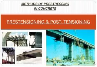
Certification for the Installation of Post-tensioning Systems by Richard Digman
PT CertificationOverview • CARES is a certification body which is accredited by the UK Government via UKAS (United Kingdom Accreditation Service). • The Crown and Tick in the CARES logo indicates Government accreditation and the registration number 0002 indicates that CARES was the second certification body to be accredited. • CARES is a specialist certification body operating in the construction industry covering: • Reinforcing and prestressing steels • Ancillary products: couplers, continuity systems, punching shear systems. • Post-tensioning contractors, post-tensioning kits.
Post-tensioningContractor Certification • CARES has two main schemes for PT contractors: • CARES PT1. for highway structures (bridges). • PT2. for flat slab construction. • Initial CARES certification requires an audit of the head office QMS and audits of all PT site activities. • Maintenance of certification requires one audit of head office and a minimum of three site audits per year.
PT Office Requirements • Quality management system to ISO 9001 • Contract review – to ensure contract requirements are met. • Purchasing – to ensure products comply with contract specification and relevant standards. • PT operative training – to ensure that only skilled operatives undertake key PT operations. • Qualified Post-tensioning system (kit). • Site quality plan and method statements covering all PT activities.
Post-tensioning Operative Training • Post-tensioning operations must be carried out by operatives with appropriate knowledge, training and proven experience. • The PT contractor must train and certify supervisors and operators to meet the requirements given in CARES Appendix PT9. • The number of inexperienced personnel (labourers for example) should be limited and be balanced according to circumstances but normally not exceed 50% of the post-tensioning personnel.
Site Requirements • Compliance with contract specification, quality plan and best practice. • Receipt and storage of materials/products. • Installation processes compliant with method statements. • Inspection and testing. • Site records.
Installation: Storage of Materials on Site • Materials must be stored on site in a way that prevents damage or deterioration. • Bagged materials have a specified shelf life and the bags are normally date marked. The material must be used by the specified date. • Strand must not be corroded!
PT System Qualification • Whole PT kit should comply with BS EN 13391 or ETAG013 which ensures: • Load efficiency of >= 95%. • Fatigue resistance >= 2 million cycles. • Anchorage can carry a load of 1.1 fpu. • Evidence of PT kit qualification should be obtained such as a product conformity certificate or test report. • The evidence should also detail the PT kit specification, it is not acceptable to mix components from different kits particularly strand types.
Strand Requirements • Strand to comply with BS 5896 and be relaxation class 2. • BS 5896 has three strand types • (a) seven-wire standard strand, • (b) seven-wire super strand, • (c) seven-wire drawn strand. • Strand should be designated in accordance with BS 5896 for example seven-wire super strand, nominal diameter 12.9 mm and nominal tensile strength 1770, class 2 relaxation is designated: • BS 5896/3 super strand - 1770 - 12.9 - relax 2.
Unbonded Tendons • Unbonded tendons are enclosed in a plastic sleeve which must be at least 1.0mm thick and made from high density polyethylene or polypropylene. PVC should not be used. • High density polyethylene is more flexible and less liable to embrittlement at extremely low temperatures, while polypropylene is more stable at high temperatures. • The friction between the coating and the strand should be no more than 60N/metre.
Duct and Vent Requirements • Duct, vent and connection material should be: • Smooth galvanised steel with a minimum wall thickness of 0.35mm. • Corrugated galvanised steel with a minimum wall thickness of 0.30mm. • High density polyethylene or polypropylene with a minimum wall thickness of 2.0mm. • PVC should not be used.
Installation: Duct, strand,anchorages …. • The duct system/tendon must be adequately fixed to resist movement and floatation during concrete placement. • Tendons should be installed to an accuracy of 5mm vertically (t/40 for slabs less than 200mm thick) and 50mm horizontally in beams and 150mm horizontally in floor slabs. • Unbonded tendons can be deviated to avoid obstructions with the agreement of the Contract Administrator (CA). • Tendons with flat ducts are relatively stiff in the transverse direction and cannot usually be deviated around obstructions. • Tendon profiles should be smooth. • Bursting Reinforcement must be concentric with the tendon.
Bursting Reinforcement(Photo by Balvac) Bursting reinforcement must be concentric with the tendon in order to be effective (the above is awaiting fixing).
Concreting(Photo by Balvac) Tendons need to be fixed to avoid displacement or flotation during concrete placement.
Location of Vents • Vents should be fixed at injection and exit points and should extend approximately 500mm above the slab surface. • Where tendon drape exceeds 500mm, intermediate vents should be fixed at tendon high points. • Intermediate vents should normally be used on tendons over 15m-20m in length.
Installation: Stressing Equipment • Stressing jacks and their load measuring system should have an appropriate and current calibration certificate, which is traceable to national standards, and no more than 6 months old at the time of stressing. • The calibration certificate should be provided by a qualified laboratory and should include a calibration curve. • The stressing equipment should be capable of establishing a tendon load to an accuracy of +/-2%.
Installation: Stressing • The post-tensioning contractor should calculate the theoretical tendon extension. • Stressing should not commence without prior agreement on theoretical extensions nor before the concrete has achieved the specified transfer strength. • The jacking force should not normally exceed 75% of the tendon’s characteristic strength • At transfer, initial prestress should not normally exceed 70% of the tendon’s characteristic strength, and in no case should exceed 75%. • Tendons should be stressed in the specified sequence and load increments.
Installation: Stressing Tendon Elongation • The prime measurement of tendon load is through the stressing jack and recorded on the stressing record. • Tendon extensions are a secondary indicative measure. • For slabs load/extensions are normally measured prior to stressing, and after stressing and locking off to an accuracy of 2% or 2mm and take into consideration the possible strand movement at the dead end anchor. • For long complex profiles such as bridge decks, multiple measurements are usually taken to allow extrapolation to determine both the elastic and non-elastic extension. • The actual extensions should normally be within +/-6% of the theoretical extensions for groups of tendons and +/-15% for individual tendons.
Extension Measurement Measurement of tendon extension at the stressing jack.
Extrapolation of Extensions Tendon extensions are usually measured at two loads points and plotted on a graph and the extension extrapolated back to the zero load point. The above graph shows approximately 25mm displacement at zero load which represents the initial slack with the system.
Installation: Grout • Steel in a stressed state is subject to accelerated corrosion, it is therefore important that tendons are quickly and correctly protected from corrosion. • It is recommended that grout is made from pre-bagged material requiring only the addition of a measured amount of water. • Grout should be batched to an accuracy of +/-2% for dry materials and +/- 1% for mixing water. • Grout made from bagged cement is non preferred because of the variability of material properties and bag weight.
Installation: Grout Properties • Grout should have the following properties, determined in accordance with the test procedures of ETAG 013 Annex C clause C.4.3.3.2. Extract from CARES Model Specification
Installation: Grout w/c Ratio • The w/c ratio should be kept as low as possible as bleed water is excess water in the grout that is not chemically bound and can lead to low density grout, grout cracking, shrinkage and porosity. • The necessary grout properties can be achieved with a properly formulated grout and the addition of minimum quantities of water.
Installation: Grouting • It is recommended that ducts are blown through with oil free compressed air prior to grouting. • Grout injection should be continuous at an agreed rate and be slow enough to avoid segregation of the grout. • The method of injecting grout should ensure filling of the ducts and complete surrounding of the steel.
Grouted Tendon(Photo Balvac) Section through grouted duct
Installation: Grout Venting • Grout should be vented from each intermediate and exit vent until it is of the same consistency as that of the injected grout. • All vented grout should be discarded. • All vents should be closed one after another in the direction of grout flow and the injection sealed off under a nominal pressure of 0.1MPa (14psi).
Installation: Post Grout Inspection • The level of grout in the injection and the vent tubes should be inspected after the grout has set. If the level of grout has fallen below the required final level or the material is degraded, all defective grout should be removed from the vent and topped up. • Grouted ducts should be protected to ensure that there is no damage to the grout due to shock or vibration for 24 hours after injection of the grout and that the temperature in the ducts does not fall below 5°C for 24 hours after injection of the grout. • Two days after grouting, the level of grout in the injection and vent tubes should be inspected and if the grout level has fallen below the top of the slab, remedial measures should be agreed with the Contract Administrator (CA). • On completion of grouting, grout vents should be cut off to slab level and positively sealed to ensure the encapsulation to the tendons is complete.
Installation: Grout Testing • Grout suitability tests should be undertaken prior to contract. • Grout acceptance tests should be undertaken during contract at the following frequencies: Extract from CARES Model Specification
Installation: Grout Testing(Photo Balvac) Fluidity testing of grout
Installation: Sealing of Anchorages • Anchorage components must be sealed against the ingress of water or aggressive agents likely to cause corrosion of the steel or anchorage. • In the case of grouted tendons, special mortars/renders and bonding agents are recommended, as mortar/render can be permeable and subject to shrinkage. • The chosen method of sealing shall be capable of resisting the specified grout pressure. • For unbonded tendons it is recommend that anchorage components are coated with grease of similar specification to that used in the tendon and that a watertight cap be applied over the coated area. The minimum concrete end cover to the cap should be 25mm.
Installation: Sealing of Anchorages (Photo Balvac) Sealing of PT anchorages against corrosion
Specification • The key to a good PT installation is a good PT specification. • The lack of guidance to specifiers has lead to some inappropriate and out of date PT specifications. • For this reason CARES has produced “Model specification for bonded and unbonded post-tensioned floors” to give guidance to specifiers. • The model spec is available for free download from www.ukcares.com