Download
1 / 28
280 likes | 366 Views
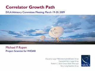
Prototype Correlator Testing. EVLA Advisory Committee Meeting, March 19-20, 2009. Michael P. Rupen. Project Scientist for WIDAR. Prototype Correlator. 4 antennas 1 GHz @ 8-bits, RCP only 4-bit re-quantization 8 x (8-128) MHz subbands 128 MHz: 1024 x 125 kHz per subband

E N D
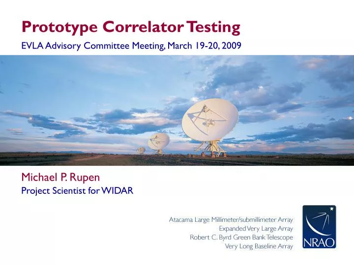
Prototype Correlator Testing EVLA Advisory Committee Meeting, March 19-20, 2009 • Michael P. Rupen • Project Scientist for WIDAR
Prototype Correlator • 4 antennas • 1 GHz @ 8-bits, RCP only • 4-bit re-quantization • 8 x (8-128) MHz subbands • 128 MHz: 1024 x 125 kHz per subband • Dumptime 0.05-1 sec • up to 7 MB/s • 1.4 GB/hr with 1sec dumps • Longest observations ~10 hours • No on-line flagging • No Tsys • No referenced pointing • CBE writes raw data scaled by data valid & FFT’d
4-station PTC • W48 = ea17 10.5km • N16 = ea18 1.4km • E72 = ea23 21.0km • N48 = ea26 9.4km 30 km
Critical On-the-sky Tests • Primary purpose of Prototype Correlator (PTC) • Designed to check for hardware problems, before going to full production • Test plan originally outlined by Carlson (2006) • Reviewed and revised by NRAO (December 2007) • Final form: Rupen (2008) • Carried out June-Dec 2008, culminating in successful WIDAR CDR
Overview of PTC CotS Tests • Dynamic fringes at 1, 5, 8, 22, 45 GHz • “Plug-&-play” • D to A configuration • Antenna changes • New StB • Phase & delay continuity when changing sources, frequencies, bands • Closure phase and channel/time averaging • Recirculation • Deep integrations: high dynamic range (72,800:1), blank field • Deep spectral line integration (3C84 HI) • “Micro”SDM+BDF to move data into CASA & AIPS
1-2 GHz: continuum + RFI 1 GHz
3C84 @ 1.5 GHz • 1244-1756 MHz • 8192 x62.5 kHz(13 km/s for local HI) 512 MHz
3C84 @ 1.5 GHz • 1244-1756 MHz • 8192 x62.5 kHz(13 km/s for local HI) HI ABQ radars VLA polarizer satellites 512 MHz
3C84 @ 1.5 GHz • 1244-1756 MHz • 8192 x62.5 kHz(13 km/s for local HI) HI ABQ radars VLA polarizer satellites Current VLA: 6.25 MHz @ 98 kHz 512 MHz
3C84 @ 1.5 GHz • 1244-1756 MHz • 8192 x62.5 kHz(13 km/s for local HI) • Final EVLA: • 512 MHz (z=0-0.3) • @ 7.8 kHz (1.7 km/s) HI ABQ radars VLA polarizer satellites Current VLA: 6.25 MHz @ 98 kHz 512 MHz
3C84 @ 1.5 GHz • 1376-1384 MHz (one 8 MHz subband) • 4096 x 1.95 kHz (0.4 km/s)
3C84 @ 1.5 GHz • 8 x 8 MHz subbands • 8 x 4096 channels • Avg’d x2 (3.9 kHz) • or x64 (470 kHz) • Zoomed in here! Tau~0.15 Tau~0.21 32 km/s 17 km/s 1382.95 MHz 1420.35 MHz Tau~0.003 430 km/s 1395.5 MHz
3C84 @ 1.5 GHz • 8 x 8 MHz subbands • 8 x 4096 channels • Avg’d x2 (3.9 kHz) • or x64 (470 kHz) • Zoomed in here! • Full EVLA: • 64 independently tunable subband pairs • Different bandwidth & resolution for each subband pair Tau~0.15 Tau~0.21 32 km/s 17 km/s 1382.95 MHz 1420.35 MHz Tau~0.003 430 km/s 1395.5 MHz
3C84 @ 22 GHz • 21988-23012 MHz • 8192 x 125 kHz (1.7 km/s) 1 GHz
3C84 @ 22 GHz • 21988-23012 MHz • 8192 x 125 kHz (1.7 km/s) • Full EVLA: • 8 GHz (BWR 1.5:1) • Full pol’n • 8192 x 1 MHz (14 km/s) 1 GHz
Recirculation:Orion water masers • 128 MHz, no recirc. • 125 kHz/channel
Recirculation:Orion water masers • 128 MHz, no recirc. • 125 kHz/channel • 64 MHz, x2 recirc. • 31.25 kHz/channel • 1.4% shown here
Recirculation:Orion water masers • 128 MHz, no recirc. • 125 kHz/channel • 64 MHz, x2 recirc. • 31.25 kHz/channel • Smoothed to match
Image not limited by closure errors • 0217+738 • 4 Jy “dot” • 2hr10min on-source • 4588-5612 MHz • Self-cal’d image • Peak:rms= 72,800:1
Deep images of strong calibrators • 4844-4972 MHz • 4972-5100 MHz • 4844-5100 MHz • 3C84: 5.2 hours • 0217+738: 2.2 hours • 0157+747: 0.8 hours • N.B. noise matches SEFD to 10% !
Deep image of a blank field • J1900+2815 • 9012-7988 MHz • 2.3 hours on-source • Rms in 125 kHz: 2.84 mJy/beam • Rms in 103 MHz (825 channels): 0.11 mJy/bm • Rms in 825 MHz (825x8 channels): 0.052 mJy/bm
PTC CotS Tests: The List • 2.1 Fringe check with delay tracking • Phase, delay vs. time • Autocorr’ns, state counts, etc. • 2.2 Phase continuity • Phase, delay consistent when changing sources, frequencies, bands • 2.3 Closure • Stability for hours • Integrates down with time and frequency averaging • Clean images • 2.4 Deep continuum observation • 10 hours
PTC CotS Tests: The List • 2.5 Spectral line consistency • Different subband bandwidths • 2.6 Subband aliasing • Leakage between subbands • 2.7 Recirculation • 2.8 Deep spectral integration
Filter response • 0217+738 • 4 Jy “dot” • 40min on-source • 7656-7784 MHz • Subband 4 • 128 MHz: Stage 1 only
Closure phase: averaging down • 0217+738 • 4 Jy “dot” • 2hr10min on-source • 4588-5612 MHz • Averages down to 0.03-0.11 degs. • Avg x2 in freq, then time • DR~ 31,000:1 • Corresponds to pol’n leakage of a few %
Averaging down in frequency • 0217+738 • 4 Jy “dot” • 40min on-source • 7784-7912 MHz • Subband 3 • 128 MHz, 1024 channels • Boxcar averaging by 4, 16, 64, 128, 256,… • Within 1% of theoretical through box=64
Averaging down in frequency • J0012+3053 • 16 mJy “dot” • 2 hours on-source • 8288-8416 MHz • subband 3 • 128 MHz, 1024 channels • Boxcar averaging: 2, 4, 8, 16, … channels • Noise goes down by sqrt(2) within 1% through box=64