Download
1 / 123
1.23k likes | 1.38k Views
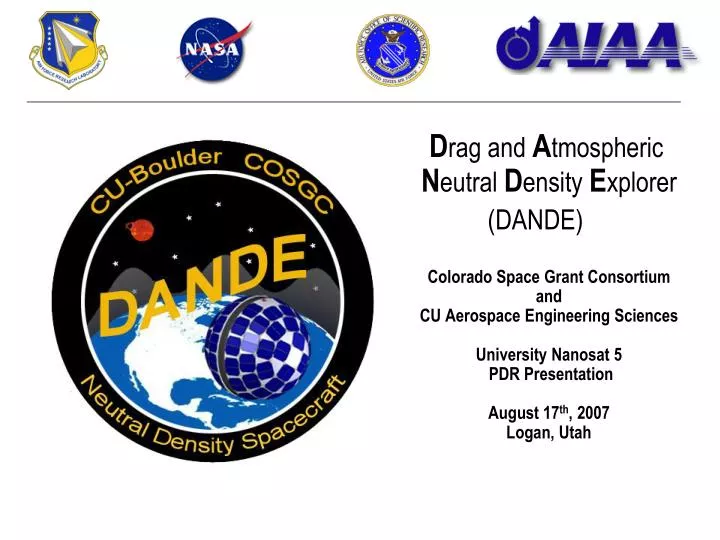
D rag and A tmospheric N eutral D ensity E xplorer (DANDE) Colorado Space Grant Consortium and CU Aerospace Engineering Sciences University Nanosat 5 PDR Presentation August 17 th , 2007 Logan, Utah.

E N D
Drag and Atmospheric NeutralDensity Explorer (DANDE) Colorado Space Grant Consortium and CU Aerospace Engineering SciencesUniversity Nanosat 5 PDR PresentationAugust 17th, 2007Logan, Utah
The Drag And Neutral Density Explorer, a satellite mission to study the thin upper atmosphere from 220 miles (350 km) down to reentry. The density of the atmosphere in this region varies greatly (300% to 800%*) due to space weather and poorly understood coupled processes. DANDE will provide valuable science data in this area, allowing current drag models to be refined and next-generation drag models to be developed, leading to: Space weather “nowcasting” in the neutral density area Precision orbit prediction with application to: Object tracking Laser comm missions Rendezvous missions Precision reentry prediction And many other applications DANDE measures atmospheric density variations using an array of highly-sensitive accelerometers, and atmospheric composition and local wind direction using a WATS (Wind And Temperature Spectrometer). DANDE will also provide coefficient of drag data based on its spherical shape and precision tracking by the USAF. DANDE weighs 110 lb (50 kg), and is 18” (0.46 m) in diameter. DANDE spins at 10 RPM to provide gyroscopic stability for instrument pointing, and ease of attitude determination and control. DANDE has body mounted solar arrays providing 30W. DANDE uses the aluminum shell halves of its structure as a receive antenna, and a piano wire embedded in Delrin as a transmit antenna. DANDE will use a novel aerobraking mechanism to quickly descend from a common 310-370 miles (500-600 km) orbit to its science orbit at 220 miles (350 km) DANDE is… * Forbes et. Al. “Thermosphere density response to the 20-21 November 2003 solar and geomagnetic storm from CHAMP and GRACE accelerometer data”, Journal of Geophysical Research, Vol. 111, June 2006
Agenda • Mission • DANDE Team • Science Payload • Bus • Ground Operations • Systems Engineering scale basketball
Mission Overview Mission Statement Explore the spatial and temporal variability of the neutral thermosphere at altitudes of 220-62 miles (350 -100 km), and investigate how wind and density variability translate to drag forces on satellites. Mission Objectives Establish and understand the relationship between total mass density, composition, and winds as functions of latitude, level of magnetic activity, and horizontal scale. Establish the relative contributions of density and winds to satellite drag as a function of latitude, level of magnetic activity, and horizontal scale. Improve understanding of the variation in coefficient of drag in the 62-125 miles (100-200 km) altitude region. Technology Demonstration Spacecraft bus to perform low-cost in-situ measurements of the drag environment Low cost acceleration measurement system Miniaturized wind sensor and spectrometer Starsys separation mechanisms
Collaboration with ANDE • Atmospheric Neutral Density Experiment (ANDE) description • Smooth outside surface • Flying three neutral mass sensors with no attitude control to measure wind and density • No photovoltaics – launches from shuttle (54 degrees inclination) fully charged (100 day lifetime) • DANDE-ANDE connection • Collaboration with Andrew Nicholas at NRL • Design: spherical receive antennas • Manufacturing: Spin-cast aluminum shells • CU’s DANDE is a complementary and unique mission • DANDE measures drag and density with accelerometers (in situ measurement) • DANDE is able to decouple wind and density variability effects due to unique suite of sensors • DANDE measures wind and composition in different orbits - scientifically very relevant! • Designed for ESPA launch with discharged batteries but still compatible with ANDE’s shuttle deployment scheme Other Neutral Atmosphere Satellites, p.64
A atmosphere ρ - density VW FD V CD tracking WATS sensor NMS sensor accelerometers solution a priori knowledge solution & a priori knowledge comparison a priori knowledge What is Satellite Drag? • Satellite Drag • Force exerted on object orbiting below 1000 km altitude, • Major orbital and attitude perturbation for low earth satellites • For a spacecraft of mass M
Objective 3 In-situ atmospheric measurements at a low cost Objective 2Relative wind and density effects on drag as a function of latitude, magnetic field & horizontal scale Objective 1Density, composition, and winds as a function of latitude, magnetic field & horizontal scale Objective 4 Coefficient of Drag variations Coefficient of Drag Measurement In-Track Wind & Cross-Track Wind Composition Measurement Density Measurement Position and Velocity Meas. Mission Lifetime & Orbit 4 5 6 2 1 3 Flow-Down To Mission Requirements Measurement requirements defined/refined in discussions with science workgroup members
Science Time Span Explanation, p.104 • Data Amount: 5 geomagnetic at 5 hours each (25h total) storms → 100 day lifetime (with margin) + 25h of quiet conditions, goal: 500h of data • Inclination: minimum required: 54º, goal: polar, sun-synchronous orbit • Initial Altitude: 350-600 • Position knowledge to ±10 km • Velocity magnitude knowledge to 50 m/s 1 2 3 4 5 6 Key Measurement Requirements *percent value based on average conditions during solar maximum, vernal equinox **assuming a wind velocity of 1 km/s
2 In-Track Wind & Cross-Track Wind Coefficient of Drag Composition Measurement Density Measurement Accelerometers Operations (Tracking) Spherical Spacecraft Mass Spectrometer Position and Time Mission Lifetime & Orbit 1 6 3 4 5 Flow Down to System Detailed Top Level Flow-Down, p.71
Mission Timeline High Altitude 310 mile (500km) Start Phase 1: LV Separation OFF - time delay - safe mode[1 day] Phase 2: Commissioning Full charge and checkout[2 days] Aerobrake deployment Aerobrake+Lightband jettison Tracking Tracking Tracking 500km altitude 350km altitude Day 0 Day 4 Day 60 Day 1 LV SEPARATION AND COMMISIONING PHASE • Phase 3: Attitude Acquire • Spin Up [12 h] • Spin-Axis Adjust [48h] • Phase 4: Science [90 days] • Adjust Spin Vector • Calibration Mode • Science Mode • Safe Mode (recharge) • Comm. Mode • Repeat Wind Composition Wind Composition Acceleration Acceleration Day 64 Day 160 QUIET CONDITIONS 4 hrs ON 2 hrs SAFE MODE GEOMAGNETIC STORMS 9 hrs ON 3 hrs SAFE MODE DOWNLINK/UPLINK ~2x in 24 hours ATTITUDE ADJUST ~1x per week RE-ENTRY DYNAMICS ~LAST WEEK OF ORBIT 125 miles – 62 miles (200 km – 100 km) SCIENCE PHASE
Program Schedule Concept Design, Requirements Definition Design Documentation, Analysis, Breadboard Verification Proto-Qualification Unit at 80%, Verification at 90% Proto-Qualification Unit at 100%, Verification at 100%, as-built documentation Detailed Schedule EDU, Analysis, Flat Sat, Verification at 50%
Co-I J. Forbes PI C. Koehler Co-I S. Palo Management M. Pilinski Advisors: C. Koehler, S. Palo Systems Engineering M. Grusin Advisor: C. Koehler, L. Curtis DESIGN TEAM COMM D. Loucks Advisor: J.White E. Keuster ADCS B. Young Advisor: T. Holden P. Axelrad C&DH B. Gilles Advisor: S. Palo EPS M. Grusin Accelerometer E. Dickey M. Edwards Advisor: S. Palo Mass Spectrometer M. Pilinski Advisors: F. Herrero, J. Forbes Thermal B. Davis, C. Kuhns Advisors: B. Poley Structures & Sep. B. Davis, C. Kuhns Advisors: P. Dukas, AJ Hoyt, B. Helgesen Software V. Singh Advisor: S. Palo DANDE Organizational Chart TEAM SKILLS Further Team Descriptions, p.65
Wiring Harness FOV360° FOV360° Acc Acc EPS EPS Photovoltaics 30W Photovoltaics 30W CDH CDH SFT SFT ACC ACC Acc Acc Acc Acc x4 x4 I2C I/O I2C I/O RAM TBD RAM TBD OS OS Battery A 14.4V 4AH Battery A 14.4V 4AH Battery B 14.4V 4AH Battery B 14.4V 4AH Inhibit Inhibit Scheduling Comm ADCS Science Scheduling Comm ADCS Science Control Control CPU AVR32 CPU AVR32 LV electrical interface LV electrical interface x4 x4 Acc Acc Acc Acc Inhibit Inhibit ABS ABS Serial I/O Serial I/O Regulation Regulation Control Control Acc Acc SSDTBD SSDTBD SEP SEP NMS NMS Instrument Instrument Mech1 Mech1 RTC RTC Instrument Instrument Lightband assy. Lightband assy. Control Control FOV32° x 1° FOV32° x 1° THM THM Coatings, Insulation Coatings, Insulation Mech2 Mech2 Control Control Sensors Sensors Control Control COM COM ADC ADC Torquerod A Torquerod A Tx Ant Tx Ant Tx 70cm 38.4kbps Tx 70cm 38.4kbps FOV90° FOV90° Control Control Torquerod A Torquerod A Instrument Instrument Mag (3-axis) Mag (3-axis) Satellite Sep Plane (SSP) Satellite Sep Plane (SSP) TNC TNC FOV 32° x 1° FOV 32° x 1° Rx 2m 9.6kbps Rx 2m 9.6kbps Rx Ant Rx Ant FOV90° FOV90° Horizon Crossing Sensor Horizon Crossing Sensor Horizon Crossing Sensor Horizon Crossing Sensor FOV 2° FOV 2° FOV 2° FOV 2° Functional Block Diagram
Exploded View Removable MGSE Brackets x2 Nutation Damper Equatorial Plate Neutral Mass Spectrometer HCI Assembly x2 Battery Box x2 Accelerometer Assembly Torque Rod Assembly x2 Brain Assembly x2 CDH Box EPS Box COM Box Separation Bracket Assembly Magnetometer X-Y CG Adjust Bracket x4 Lightband Bracket Assembly
Science Payload InstrumentLead EngineerAdvisor Accelerometer E. Dickey S. Palo Neutral Mass Spectrometer M. Pilinski F. Herrero
Requirements Accelerometer (ACC) • Major Driving Requirements • Measure drag induced acceleration to a precision of 10 nano-g’s • Measure acceleration in a ± 100 μg range • Output acceleration to the desired precision at least once every 60 seconds • Verification Method • Acceleration analysis and testing • Acceleration analysis with complete system testing • Advisor • Professor Scott Palo, CU-Aerospace Requirements detail, p.80
Design Accelerometer (ACC) Band pass filter removes DC offset and high frequency noise Built in temperature sensor 4th order polynomial corrects for scale factor drift Digital post-processing computes acceleration solution Data averaged from all 6 sensors Temperature effects removed Sinusoidal signal profile allows for bias removal Short wiring path from sensor to filter board
Testing Accelerometer (ACC) • Accelerometer Simulation Model • Measure spectral noise profile, voltage scale factor, temperature effects • Determines requirements for: • Filtering • Amplification • Digital post-processing • Test complete system build to verify all design requirements met • Revise and retest design if necessary • 2 Honeywell accelerometers on-hand (donated)
Science Mode ACC-2 ACC-4 ACC-1 ACC-6 ACC-3 ACC-5 AVERAGE a = 1.00 ± 0.01ug FD
Requirements Neutral Mass Spectrometer (NMS) Major Driving Requirements range from 13 ± 2 amu to 31 ± 2 amu. measure the number densities to a one sigma accuracy of ±1.5x10¹² m-3 and a precision of 1.0x10¹² m-3. measure wind magnitude with a 1-sigma precision of +/- 100m/s. Verification method Calibration testing Error analysis Advisors Dr. Fred Herrero, GSFC, NASA Requirements detail, p.74
Built at CU with Goddard design Built by Goddard Design Neutral Mass Spectrometer (NMS) • 3 major sub-assemblies • Neutral Mass Spectrometer • Wind and Temperature Spectrometer • Electronics and Power Box • ~1 kg mass, 3in x 3 in x 3in • Maximum voltage – 100 V (ion source) • Neutral Mass Spectrometer and Wind Sensor both mounted on electronics box NMS/WATS Electronics Box NMS Sensor Head
Principles and Testing Neutral Mass Spectrometer (NMS) • Vacuum Testing calibration performed at Goddard • Electrostatic Mass Analyzer • output detected by Micro-Channel Plate (MCP) mounted on a circuit board • Wind and Temperature Spectrometer • Angled channels give angular distribution • [Faraday cups] determine the particle flux in each channel
unknown errors sample rates & instrument precision Science Error Analysis and Budget • Error budget evolution • RMS sum of errors spreadsheet → Monte Carlo Error Simulation → Mission Simulator • Purpose: try to break the measurement method and algorithms – how robust is it?
Spacecraft Bus SubsystemLead EngineerAdvisor(s) Attitude Control B. Young T. Holden Structures and Separation B. Davis P. Dukas, AJ Hoyt B. Helgesen Thermal Control B. Davis B. Poley Aero-Braking M. Grusin S. Palo
Requirements Attitude Determination and Control (ADC) • Driving Requirements • Knowledge: <1° in TNR frame • Pointing: <5 ° in TNR frame • ConOps Schedule: spin-up in 24 hrs, align in 48 hrs • Verification Method • Analysis • Advisors • Tim Holden, Ball Aerospace • Siegfried Auer, Optics Consultant Requirements detail, p.81
Analysis Attitude Determination and Control (ADC) • Spin stabilization about orbit normal • 40°/sec (10 rpm) • Only two maneuvers: spin-up and axis alignment • Sensors • Magnetometer for spin-up • Horizon Crossing Indicators for spin axis alignment • Actuators • Torque rods: one along spin axis and one transverse • Nutation damper
Analysis Attitude Determination and Control (ADC) • Performance Characteristics • ConOps requires spin-up < 24 hrs, alignment < 48 hrs • Closed loop spin-up • Open loop alignment: upload correctionmaneuver over every ground station pass • Hardware status • Magnetometer: plan to buy COTS by 1SEP07 • HCI: narrowed to two vendors, issue purchase order by 1SEP07 • Torque Rods: make in house, currently in production • Nutation damper: still analyzing necessity. Can make in-house. SIMULATED SPIN-UP MANEUVER
Requirements Structure and Separation (STR/SEP) • Major Driving Requirements • Smooth spherical exterior, no more than 15% (goal 10%) of the exterior projected area shall reflect incoming particles in a non-spherical fashion. • Ease of adjusting the spacecraft center of gravity with an offset no greater than 1 centimeter. • Hemispheres electrically isolated from equatorial plate. • Verification Method • Verified by Numerical Analysis / CAD modeling • Demonstration • Advisors • Poti Doukas of Instar Engineering and Consulting, Inc. • Bryan Helgesen and AJ Hoyt of SpaceDev, Inc. Requirements detail, p.78
Design Structure and Separation (STR/SEP) Equatorial Plate-Spacecraft Backbone, supports all interior components-Al 6061-T6, 16.5 inch OD Delrin Insulating Ring-Supports the hemispheres and receiving antenna Spherical Shells-Supports only the solar arrays and ballast masses, acts as the transmit antenna-Al 6061-T0, 18 inch OD, 1/16th skin thickness-Manufactured by Caywood Metal Spinning, INC Mechanism Assembly-Contains 2 Starsys Low-Shock Release Mechanisms-Al 6061-T6 Lightband Adapter Bracket-Interfaces between the Sphere and Lightband-Al 6061-T6, 15.5 inch OD-Discarded after ejection CG Management-Interior layout based on even mass distribution-Ballast to be placed at discrete points on the interior of the hemispheres for fine-tuning Satellite Lifting MGSE-Single cable to be attached along the perimeter of equatorial plate MGSE detail, p.96
Structural Analysis Structure (STR) • Finite Element Analysis -Using Cosmos 2006 -Validating by comparing results with closed form solutions • Structural Status • Preliminary analysis of primary structure complete. • Working on full analysis of Lightband bracket • Natural Frequency • Calculated with simplified model in FEA. Lightband Bracket stiffened to raise natural frequency Worst Case Loading on Lightband Adaptor BracketRed is where the Margin of Safety >= 0.08 Safety Margin detail, p.86 Natural Freq detail, p.90 Data from Doc# UN5-STR104.0_Preliminary_Structural_Analysis
Separation System Analysis Separation System (SEP) • Calculations Show That: • Need to have more than one mechanism (lateral loading found to be worst case) • Minimum required Pre-Load is 4408 lbf. • Bracket to be released at 1 m/s • See Backup Slides • Interaction with Starsys • Have been in close e-mail / telephone contact and have held monthly meetings • Acting as an advisor • Deployment and Mechanism Video • Mechanism Details • Max preload of 5000 lbf • Does not restrain shear load • Fully electrical and mechanical redundancy • Paraffin actuator • Will reach a TRL-6 by Q3, 2007 Ejection speeds detail, p.95 Preload detail, p.91
Design Separation System (SEP) Separation Interface: • Cup/Sphere restricts translational movement. Trench/Sphere restricts rotational movement. • Kinematic mounts combined with peelable Al shims allow for machining tolerances • Kinematic mounts different materials to avoid stiction. Likely materials: Titanium and/or super alloys. • Redundant Paraffin actuators coupled between mechanisms • Each mechanism centered about three legs release timing less critical • Springs captured with bracket release • Concerns: • Shear Loading within Cup/Sphere • Machining Tolerances
Requirements Thermal (THM) • Major Driving Requirements: • Provide thermal analysis to show that proper protection is met during all phases of the mission • Heat sources and respective profiles are supplied to AFRL • Establish critical temperatures for all 4 modes of operation (Operating, Non-Operating, Survival, Safety) • Verification Methods: • Demonstration • Advisors • Robert Poley of Ball Aerospace • Driving constraints: • Components need to be thermally conductive to spherical skin • Small available radiative surface • Long duration instrument on/off times Requirements detail, p.79
Design Thermal (THM) • Transient analysis performed • Single Node Model • Spherical Shape • Cold Case ß=0˚ • Hot Case ß=72˚ • Results: • Hot Case~25˚ ±1˚ C • Cold Case~ -7˚ ±3˚ C -See backupslides • Next steps: • Discuss why the model is running colder than predicted • Integrate with Thermal Desktop software • Continue working with established contacts in industry Analysis detail, p.98 Transient charts, p.100 Data from Doc# UN5-THM101.0_Preliminary_Thermal_Analysis
Concept Aerobraking System (ABS) Allows rapid descent from high orbits (600km) to our science orbit (350km) Order of 100 to 200 days instead of many years Increases launch opportunities Mounts to Lightband Adapter Bracket Occupies unused volume Jettison ABS with rest of Lightband Adapter Bracket Optional component Will be developed in parallel with rest of spacecraft Can be removed without affecting rest of system if lower-altitude launch is available DANDE orbit altitude (polar orbit, launch 1/1/2010) DANDE orbit altitude (polar orbit, launch 1/1/2010) 600 600 600km starting 600km starting altitude altitude 550 550 500 500 500km starting 500km starting altitude altitude Mean altitude (km) Mean altitude (km) 450 450 400 400 56 days 7.4 years 7.4 years 21 years 21 years 225 days 350 350 0 0 1 1 2 2 3 3 10 10 10 10 10 10 10 10 Time since launch (days) Time since launch (days) No ABS 10 sq. ft (1m2) 43 sq. ft. (4m2) No ABS
Spacecraft Electrical SubsystemLead EngineerAdvisor(s) Electrical M. Grusin G. Hunyadi Command & Data Handling B. Gilles S. Palo Software V. Singh S. Palo Communications D. Loucks J. White, E. Kuester
Requirements Electrical Power System (EPS) • Major Driving Requirements • Meet the voltage and power needs of the subsystems • Perform the functions required by the Design Reference Mission • Adhere to all NS5 safety regulations • Verification • Mission Analysis, Functional Testing • Advisors • B. Sanders (COSGC) Requirements detail, p.82
X 3 X 3 X 1 X 1 Design Electrical Power System (EPS) PHOTOVOLTAICS INHIBITS BATTERIES / CHARGING INHIBITS REGULATION CONTROL SUBSYSTEMS 30 watts, 4 volts, 7.5A BoostConverter Main Bus, +14V Unregulated output Solid-State Relays Chargecontrol A Chargecontrol B Switching Converters Converter Regulated outputs Converter + + Converter Latchingrelays Latchingrelays Battery A 14.4V 4000mAh Battery B 14.4V 4000mAh _ _ Ground lines to subsystems Single-point Chassis ground • INPUT • 30 Watt output photovoltaic panel (~150 Spectrolab dual-junction cells, 21.5% efficient) • STORAGE • Two battery stacks, 12 x 1.2V NiCd cells each, 8AH total • OUTPUT • Unregulated +14V, regulated +5V, +12V, +15V, -15V • Voltage and current sensors TBD EPS detail, p.105 Inhibits detail, p.106
off on % Power Budget Electrical Power System (EPS) Four major operating modes: SAFE MODE SEPARATION MODE (5 minutes HOP fire) 15.2 WH Watt-hours required / orbit 19.2 WH Watt-hours required ACC ACC ADC ADC 28.0 WH Watt-hours available / orbit 28.0 WH Watt-hours available / orbit COM TX COM TX COM RX COM RX CDH Power surplus / deficit CDH 13.7 WH Power surplus / deficit 8.8 WH EPS EPS NMS NMS indefinitely 36 minutes Sustain time (continuous HOP fire) Sustain time (to 25% DOD) SEP SEP NA 3.3 hours Recovery time (safe mode) Recovery time (safe mode) SPIN-UP MODE SCIENCE / CALIBRATION MODE 31.8 WH 32.5 WH Watt-hours required / orbit Watt-hours required / orbit ACC ACC ADC ADC 28.0 WH 28.0 WH Watt-hours available / orbit Watt-hours available / orbit COM TX COM TX COM RX COM RX CDH CDH Power surplus / deficit -4.1 WH Power surplus / deficit -4.8 WH EPS EPS NMS NMS 11.2 hours 9.6 hours Sustain time (to 25% DOD) SEP SEP Sustain time (to 25% DOD) 3.3 hours 3.3 hours Recovery time (safe mode) Recovery time (safe mode) More detail, p.107 Power deficits handled operationally (run for a period then recharge)
Requirements Command and Data Handling (CDH) Requirements detail, p.83 • Major driving requirements • Process and store science data • Operate in the space environment at 370 miles (600 km) and below over a 400-day life-span • 300 day Aero-Braking (safe mode) • 100 day science mission (operational modes) • CDH shall meet the Electrical Design Requirements as per Nanosat-5 User’s Guide • Electrical Safety and Material Requirements • EMI/EMC Analysis and Testing • Verification Method • Functional Testing • COTS TID failure rating comparison with CREME96 predicted TID • Design inspection and tabular analysis of currents, voltages, and frequencies • Advisor: S. Palo
Design Command and Data Handling (CDH) • Meets Requirements: • Processing and storage are well within AVR32 capabilities • COTS components survive > 2-10 krad TID • CREME96 estimates < 0.3 krad worst case over mission life with 100 mil shielding. Design detail, p.109
Requirements Software (SFT) • Major Driving Requirements • Act as an interface between CDH and other subsystems • Store science and engineering data • Operate spacecraft modes: Science mode, Safe mode, Separation mode etc. • Provide capability to upload new code during mission • Detect and report errors • Verification Method • Functional testing • Advisor • Professor Scott Palo, CU-Aerospace Requirements detail, p.79
SCIENCE MODE Subsystems Polling Routine ACC NMS ADC …… Input Buff Input Buff Input Buff Input Buff Output NMS Process ADC Process ACC Process Process ACC Output NMS Output ADC Output … .. Output Buffer Buffer Buffer Buffer Data Uplink / Downlink RS - 232 Flash - File COMM COM System Process Software Architecture • Major functional blocks • Comm interface (RS-232 / TNC) • Subsystem interface (I2C) • Data storage interface (FLASH) • Mode operations • Development • Linux operating system • AVR32 hardware environment • Flight programming in C
Requirements Communications (COM) • Major Driving Requirements & Constraints • Data Rates • Uplink 9600 baud • Downlink 38400 baud • Minimum up/down-link margins of 10dB • Minimum up/down-link BER of 10-5 • Structural envelope of a sphere • Verification • Link and data budget • Functional testing • Advisors • Jim White, USAFA (retired/Colorado Satellite) • Edward Kuester, Professor, CU Electrical Engineering Reqts detail, p.77
Analysis Communications (COM) ■2m Receive Slotted sphere antenna 2 hemispheres shorted on one side Beamwidth to ½ power: 90º +/- 70º gain: -9.82dBi Max gain: 2.14 dBi ■70cm Transmit 4 sections piano wire Set in Delrin ring Beamwidth to ½ power: 140º +/- 70º gain: -2.21dBi Max gain: 2.55 dBi More detail, p.112
Downlink 38.4k 70cm antenna SYMEK TNC31S TX/RX** Downlink 38.4k LNA 2m antenna 9.6k/38.4k dual modem Computer Uplink Downlink Uplink 9.6k LNA 70cm antenna SYMEK TNC3S TX/RX** Downlink 38.4k 2m antenna 9.6k/38.4k sep modem Computer Uplink 9.6k Design Communications (COM) System Block Diagram Satellite Ground On hand/ordered In development
Basic Data Minimum Elevation from Boulder: 10º Mission Slant Range: ~354 miles (570 km) Frequency: Downlink:70cm band (~435MHz) Uplink: 2m band (~145MHz) Data Rate Uplink: 9600 baud Downlink: 38400 baud Uplink Budget Carrier Margin achieved: 78.04dB Data Link Margin achieved:18.55dB Downlink Budget Carrier Margin achieved: 77.66dB Data Link Margin achieved: 12.15dB Analysis Communications (COM) More detail, p.111
Ground Systems Ground Operations and Comm Science Data Assimilation
Requirements Ground Operations (GND) • Major Driving Requirements • Receive and spacecraft science and health data • Save all spacecraft data to redundant storage • Statistically determine the spin of the spacecraft and produce a mission history of the spin variables • Upload commands to the ADS system to keep the spin axis within its pointing cone • Verification • Functional Testing with Ground Station and flat-sat unit • Advisors • T. Holden (Ball Aerospace) Requirements detail, p.75
Design Ground Operations (GND) TRACKING AFSPC/A9A Partnership ORBIT DATA ECI Position(t) ECI Velocity(t) Attitude Determination (Kalman) DATA BACKUP ATTITUDE DATA HCI Data (t) Magnetometer Data (t) PROCESSED ATTITUDE DATA Spin Vector (t) Spin Rate (t) DATA BACKUP DATA BACKUP GROUND COMM PASSSEQUENCING SCIENCE DATA RTN Wind Angle (t) Number Fluxes (t) Acceleration (t) Attitude Prediction and Control “…it is my goal to help the DANDE team achieve their objectives to that end through scientific advising and tracking support.”– Bruce Bowman AFSPC/A9A DATA BACKUP ATTITUDECOMMANDS Bx (t) By (t) SC HEALTH DATA DATA BACKUP DATA BACKUP MISSIONPLANNING SPACEWEATHER NOAA SEC