Download
1 / 42
450 likes | 647 Views
How Do You Qualify Heat Shields on Earth? . April 14, 1982 Space Shuttle Columbia STS-003 Kuiper Airborne Observatory Infra-Red image. Or: Electric Arc Jet Testing at NASA Ames. 1998 Ames IHF arc jet facility Ablating disk with bow shock. CSC/SETI Institute Colloquium Series.

E N D
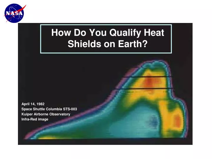
How Do You Qualify Heat Shields on Earth? • April 14, 1982 • Space Shuttle Columbia STS-003 • Kuiper Airborne Observatory • Infra-Red image
Or: Electric Arc Jet Testing at NASA Ames • 1998 • Ames IHF arc jet facility • Ablating disk with bow shock
CSC/SETI Institute Colloquium Series • December 2004 • MeridianiPlanum • Mars Exploration Rover Opportunity • Heat shield and impact site • July 29, 2009 • John Balboni • Thermo-Physics Facilities • NASA Ames Research Center
Heat Shields: Impact on Science • Heat Shield: ~10% of landed mass • 820 kg (rover, lander, heatshield, parachute) • ~$820,000,000 for two Mars Rovers (APPROXIMATE) • ~$500,000 per kg landed mass (two rovers) (APPROXIMATE) • two Heat Shields cost ~$80,000,000 (APPROXIMATE)
Galileo Jupiter Probe: 1995 • Galileo entry probe was 45% heat shield: 150 kg “dead” wt. • Mass • Mass • Mass • Science payload • mass is inversely • proportional to • the “delivery” mass, • including the heat shield
Columbia STS-107: April 1, 2003 • Heat shield failure may lead to complete failureof the mission and loss of the spacecraft
X-37 FALCON/CAV PAET NASP X-33 SHARP B1 & B2 APOLLO MARS PATHFINDER PHOENIX VIKING PIONEER-VENUS GALILEO MAGELLAN STARDUST MER Orion SPACE SHUTTLE Rationale for Arc Jet Testing • R&D: provide critical data for the research and development of thermal protection (TPS) materials • Flight Qualification/Sustaining Engineering: qualify/certify TPS materials and processes for National Programs • Instrumentation: Develop surface and in-depth instruments and sensors • Space Ops: Support TPS damage assessment and verification of repair techniques for crewed spacecraft • Space Shuttle • Tile Damage
Acknowledgements • Contributions and charts provided by: • Dr. Michael Wright, NASA Ames • Dr. George Raiche, NASA Ames • Dr. Bernie Laub, NASA Ames • Ernest Fretter, NASA Ames • Bonnie James, NASA Marshall Space Flight Center
Summary: • The Problem (and Solution) • The Analyses • The Experiments • The Facilities
Stardust Mission: Video • (play video here)
The Root Problem: Speed • Physics dictates high speeds for space travel. Consider • circular orbits at 1.025 x Radius: • Satellite Speed Escape Speed • Mars . . . . . . . . 3.5 km/sec 5.0 km/sec • Venus . . . . . . . 7.2 km/sec 10.3 km/sec • Earth . . . . . . . . 7.8 km/sec 11.2 km/sec • Jupiter . . . . . . 41.7 km/sec 59.5 km/sec • Kinetic Energy ~ mV2 • Surface Convective Heat Transfer Rate ~ V3
The Solution: Blunt Bodies • MSL = Mars Science Laboratory (rover); 2011 Launch
AIM-22 Tile Gap Fillers RCG Coating FRCI-12 Tile The Space Shuttle: Thermal Protection TUFI/AETB Tile AFRSI Blanket
Hypersonic Flight: Analysis • CFD = Computational Fluid Dynamics
Hypersonic Flight: Analysis • Except for Space Shuttle, all past Earth entry vehicles and all planetary entry vehicles use “Ablative” heat shield materials. • TPS = Thermal Protection Sysetm (Heat Shield)
Arc Jet Test Objective Verify on the ground the heat shield integrity before atmospheric entry Example: Develop and characterize material properties Screen candidate materials Verify heat shield design: gaps, attachments Develop and characterize instrumentation Verify heat shield repair techniques
Calibration Data and Pre-Test Predictions Arcjet Diagnostics and Analysis: Flight Traceability example Arc Jet flow analysis determines appropriate arc jet test configuration and in-depth material response Aerothermal analysis predicts the flight environment Entry vehicle shape is established, MER aeroshell CFD solution of TIRS cover and backshell TPS arc jet test in PTF in 3D with chemically reactions in the flow and at the surface and 3 TIRS rockets with covers were added at a late date Arc jet diagnostics measure the free-stream conditions and material response Comparing experimental and modeling data confirms arcjet-to-flight correspondence TPS is sized to the aerothermal environment; Final arc jet tests establish TPS flight certification MER TIRS flight article Photo of TIRS arc jet test in PTF
Space Shuttle Wing Leading Edge Repair Pre-test: 9x9 inch panel with 7’’ plug repair 15 min. arc-jet test; exceeding 2000 C on the material
Arc Jet Complex STATUS: Operational (Commissioned 1962) LOCATIONS: N-234 and N238 • Four Arc-Jet Facilities: • Aerodynamic Heating Facility (20 MW) • 2-By- 9-Inch Supersonic Turbulent Flow Duct (20 MW) • Panel Test Facility (20 MW) • Interaction Heating Facility (60 MW) One of only three such facilities in the US; (Two NASA, One DoD)
Arc Jet Panel Test Panel test in semi-elliptical flow nozzle; side view; 80 cm x 80 cm Flow IR image of tile panel; Top view
Arc Jet Schematic Objective: Simulate entry heating in a ground-test facility Goal: Verify a thermal protection material/system design before flight; support continuing engineering during operations ARC HEATER NOZZLE TEST CHAMBER High Energy Flow Mach 5 - 7 at exit 10-45 MJ/kg Vacuum Test Chamber Gas Temp. > 8,000 K Simulates altitudes 30–60 km Method: Heat a test gas (air) to plasma temperatures by an electric arc, then accelerate into a vacuum chamber and onto a stationary test article
Ames High Enthalpy Test Facilities Aerodynamic Heating Facility 20 MW - TPS Free Jet Testing Interaction Heating Facility 60 MW - TPS Free Jet and Panel Testing Panel Test Facility 20 MW - TPS Panel Testing 2”x9” Turbulent Flow Duct 20 MW - TPS Panel Testing
Arc Jet Test Samples Arc Jet Photo
Arc Jet Walk-Around • (play video here)
Arc Jet Test • (play video here)
Scenario: Lunar Exploration All lunar sorties require Earth return entry vehicle: EXAMPLE ONLY Reference ESAS Requirements Study, June 1, 2005
Candidate CEV Configuration Ames is positioning itself for a major role in TPS design Reference ESAS Requirements Study, June 1, 2005