Download
1 / 22
260 likes | 526 Views
Lecture 6 Basic physical principles of computed tomography & Image formation. Advanced Biomedical Imaging. Dr. Azza Helal A. Prof. of Medical Physics Faculty of Medicine Alexandria University. Points to be covered Linear Tomography Components of computed tomography unit

E N D
Lecture 6 Basic physical principles of computed tomography & Image formation Advanced Biomedical Imaging Dr. Azza Helal A. Prof. of Medical PhysicsFaculty of MedicineAlexandria University
Points to be covered • Linear Tomography • Components of computed tomography unit • Basic data acquisition • CT scanner generations • Principle of CT imaging • CT number & its clinical application • Windowing.
Linear Tomography: (single slice imaging) Method of imaging single slice of object parallel to film and placed at a specific point (fulcrum) which is adjusted to height of anatomy of interest.
Tube and film moves from 1st position to the 2nd , all points in focal plane project to same position on the film • Points above or below the focal plane do not project to the same film position and are blurred. • By changing the relative motion of the film and tube the focal plane can be adjusted upward or downward • It is useful in IV urography • Body imaging tomography (Computed tomography) (CT): Reconstruction by a computer of an image of a plane or slices of an object.
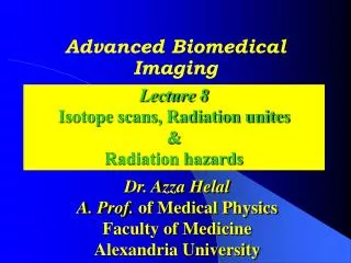
X-ray Tube X-ray Beam CT Table Detectors 2. Components of CT unit Table,scanning gantry (x-ray source & detector array) x-ray generator, computer and viewing consoles. 5
Probing patient from different directions during 360 rotations with x-ray beam of known intensity (I0) & measuring it after it has passed the pt (I) using detectors. Detector (Scintillator / ionization chambers) measures exiting x-ray beam (I) & converts it into a proportional signal current. From I & I0, (U) is calculated (reflect intensity of photon beam attenuated) I=I0e-ux
u is different for different tissue density. Image is developed from multiple measurements of x-ray u detected from exterior of the patient. By solving a system of linear equations for several projections, value of u can be computed.
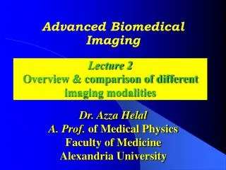
4. CT scanner generations 4. CT scanner generations 1st: singlebeam & detector. Translate - rotate 2nd :narrow fan beam / detector array. 3rd:wide fan beam / detectors array, bothrotate 4th:x ray tube alone rotates / stationary detectors. 5th :multiple x ray tubes & multiple stationarydetectors to scan multiple slices simultaneously.
4. CT scanner generations 2nd 1st 4th 3rd
5. Principle of CT imaging • To allow the computer to present this information with a large scale, a reference material is used (water). Why? its µ is close to those of soft tissues. • CT number is calculated as a relative comparison of x-ray attenuation of a voxel of tissue to equal volume of water. • CT number of each voxel (average of individual CT no of the contents of corresponding voxel) is computed & stored in computer memory.
The Hounsfield scale • . • large amount of data presented as grey scale (whiteness is α average µ of contents /voxel). • Tissues appear as shades of gray from black & white. • Tissues with high u (bone) appear white • Tissues with low u (air) appears black. • bone= 1000 water= 0 air= -1000
CT number (reflect density) Air = -1000, Lung -550 to -950 Fat=-80 to -100 Water = 0 White matter = 20-30, Gray matter = 35-45 soft tissue +40 to +60 depends on KV Acute Hge = 70 to 100 HU Calcification = 200 to 300 HU Bone +500 to +1500 Contrast agent +3000
CT tissue characterization CT Numbers or Hounsfield Units
Windowing • Selective display of a restricted range of gray scale of selected tissues (tissues of interest). • Tissues with CT no outside this window un displayed. • Manipulated by selection of : • window center. • window width
Window level is CT number selected for centre of the range of numbers displayed on the image. • Window width is total range of values selected. • Width determines contrast. • A narrow window enhances inherent contrast. • Window level determines the brightness
Centre average gray <centre lighter gray >centre darker gray W = 80 C = 30 W = 80 C = 50 W = 50 C = 30 W = 80 C = 20 W = 200 C = 30
In routine work • Brain is visualized at level 30 and width 80. • Soft tissue is visualized at level 40 and width 250. • Bones are visualized at level 1000 & width 2000. • Lungs are visualized at level -600 & width 1500. • As CT no reflects u and so different tissues densities, • So it is used to characterize normal tissues & pathologies as calcification & lesion diameter.
Questions • Define; window level & width? • What are the detectors used in CT unit? • What is the CT number of bone, air and water? • What is the difference between u and CT number of the tissue?