Download
1 / 262

E N D
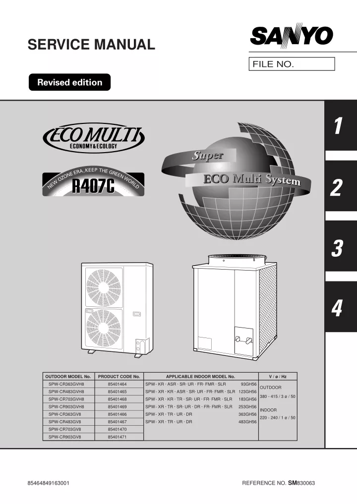
SERVICE MANUAL FILE NO. 1 2 3 4 0409_C_S OUTDOOR MODEL No. PRODUCT CODE No. APPLICABLE INDOOR MODEL No. V / ø / Hz SPW-CR363GVH8 85401464 SPW- KR · ASR · SR· UR · FR· FMR · SLR 93GH56 OUTDOOR SPW-CR483GVH8 85401465 SPW- XR · KR · ASR · SR· UR · FR· FMR · SLR 123GH56 380 - 415 / 3 ø / 50 SPW-CR703GVH8 85401468 SPW- XR · KR · TR · SR· UR · FR· FMR · SLR 183GH56 SPW-CR903GVH8 85401469 SPW- XR · TR · SR· UR · DR · FR· FMR · SLR 253GH56 INDOOR SPW-CR363GV8 85401466 SPW- XR · TR · UR · DR 363GH56 220 - 240 / 1 ø / 50 SPW-CR483GV8 85401467 SPW- XR · TR · UR · DR 483GH56 SPW-CR703GV8 85401470 SPW-CR903GV8 85401471 REFERENCE NO. SM830063 85464849163001
Important Please Read Before Starting When Installing …………………………………………………………………… …In a Room Properly insulate any tubing run inside a room to prevent “sweating” that can cause dripping and water damage to walls and floors. This air conditioning system meets strict safety and operating standards. As the installer or service person, it is an important part of your job to install or service the system so it operates safely and efficiently. …In Moist or Uneven Locations Use a raised concrete pad or concrete blocks to provide a solid, level foundation for the outdoor unit. This prevents water damage and abnormal vibration. For safe installation and trouble-free operation, you must : ⓦ Carefully read this instruction booklet before beginning. ⓦ Follow each installation or repair step exactly as shown. ⓦ Observe all local, state, and national electrical codes. ⓦ Pay close attention to all warning and caution notices given in this manual. …In an area with High Winds Securely anchor the outdoor unit down with bolts and a metal frame. Provide a suitable air baffle. …In a Snowy Area (for Heat Pump-type Sys- tems) Install the outdoor unit on a raised platform that is higher than drifting snow. Provide snow vents. This symbol refers to a hazard or unsafe practice which can result in severe personal injury or death. When Connecting Refrigerant Tubing …………………………………………………………………… • Ventilate the room well, in the event that refrigerant gas leaks during the installation. Be careful not to allow contact of the refrigerant gas with a flame as this will cause the generation of poisonous gas. This symbol refers to a hazard or unsafe practice which can result in personal injury or product or property damage. CAUTION • Keep all tubing runs as short as possible. If Necessary, Get Help These instructions are all you need for most installation sites and maintenance conditions. If you require help for a special problem, contact our sales/service outlet or your certified dealer for additional instructions. • Use the flare method for connecting tubing. • Apply refrigerant lubricant to the matching surfaces of the flare and union tubes before connecting them, then tighten the nut with a torque wrench for a leak-free connection. In Case of Improper Installation The manufacturer shall in no way be responsible for improper installation or maintenance service, including failure to follow the instructions in this document. • Check carefully for leaks before starting the test run. NOTE Depending on the system type, liquid and gas lines may be either narrow or wide. Therefore, to avoid confusion the refrigerant tubing for your particular model is specified as either “narrow” or “wide” rather than as “liquid” or “gas”. SPECIAL PRECAUTIONS When Wiring …………………………………………………………………… ELECTRICAL SHOCK CAN CAUSE SEVERE PERSONAL INJURY OR DEATH. ONLY A QUALIFIED, EXPERIENCED ELECTRICIAN SHOULD ATTEMPT TO WIRE THIS SYSTEM. When Servicing …………………………………………………………………… • Turn the power OFF at the main power box (mains) before opening the unit to check or repair electrical parts and wiring. • Do not supply power to the unit until all wiring and tubing are completed or reconnected and checked. • Keep your fingers and clothing away from any moving parts. • Highly dangerous electrical voltages are used in this system. Carefully refer to the wiring diagram and these instructions when wiring. Improper connections and inadequate grounding can cause accidental injury or death. • Clean up the site when installation is finished. Check that no metal scraps or bits of wiring have been left inside the unit. • Ground the unit following local electrical codes. CAUTION • Connect all wiring tightly. Loose wiring may cause overheating at connection points and a possible fire hazard. When Transporting …………………………………………………………………… • Ventilate any enclosed areas when installing or testing the refrigeration system. Contact of refrigerant gas with fire or heat can produce poisonous gas. • Confirm after installation that no refrigerant gas is leaking. If the gas comes in contact with a burning stove, gas water heater, electric room heater or other heat source, it can cause the generation of poisonous gas. Be careful when picking up and moving the indoor and outdoor units. Get a partner to help, and bend your knees when lifting to reduce strain on your back. Sharp edges or thin aluminum fins on the air conditioner can cut your fingers. i
Check of Density Limit Important 2 : The standards for minimum room volume are as follows. No partition (shaded portion) The room in which the air conditioner is to be installed requires a design that in the event of refrigerant gas leaking out, its density will not exceed a set limit. The refrigerant R-407C which is used in the air condi- tioner is safe, without the toxicity or combustibility of ammonia, and is not restricted by laws to be imposed which protect the ozone layer. However, since it contains more than air, it poses the risk of suffocation if its density should rise excessively. Suffocation from leakage of R-407C is almost non-existent. With the recent increase in the number of high density buildings, however, the installation of multi air conditioner systems is on the increase because of the need for effective use of floor space, individual control, energy conservation by curtailing heat and carrying power etc. Most importantly, the multi air conditioner system is able to replenish a large amount of refrigerant compared with conventional individual air conditioners. If a single unit of the multi air conditioner system is to be installed in a small room, select a suitable model and installation procedure so that if the refrigerant accidentally leaks out, its density does not reach the limit (and in the event of an emergency, measures can be made before injury can occur). In a room where the density may exceed the limit, create an opening with adjacent rooms, or install mechanical ventilation combined with a gas leak detection device. The density is as given below. NOTE (1) 0001_M_I (2) When there is an effective opening with the adjacent room for ventilation of leaking refrigerant gas (opening without a door, or an opening 0.15% or larger than the respective floor spaces at the top or bottom of the door). Outdoor unit Refrigerant tubing Indoor unit 0002_M_I (3) If an indoor unit is installed in each partitioned room and the refrigerant tubing is interconnected, the smallest room of course becomes the object. But when a mechanical ventilation is installed interlocked with a gas leakage detector in the smallest room where the density limit is exceeded, the volume of the next smallest room becomes the object. Refrigerant tubing Total amount of refrigerant (kg) Outdoor unit Min. volume of the indoor unit installed room (m3) Density limit (kg/m3) > Very small room Indoor unit The density limit of R-407C which is used in multi air conditioners is 0.3 kg/m3. Small room Mechanical ventilation device - Gas leak detector Medium room Large room 0003_M_I 1 : If there are 2 or more refrigerating systems in a single refrigerating device, the amount of refrigerant should be as charged in each independent device. NOTE NOTE 3 : The minimum indoor floor space com- pared with the amount of refrigerant is roughly as follows. (When the ceiling is 2.7 m high) m3 m2 Outdoor unit 50 135 e.g., charged amount (10 kg) Range below the density limit of 0.3 kg/m3 (Countermeasures not needed) e.g., charged amount (15 kg) 45 121.5 (when the ceiling is 2.7 m high) 40 108 35 94.5 Min. indoor floor area Min. indoor volume 30 81.0 25 67.5 Range above the density limit of 0.3 kg/m3 (Countermeasures needed) Room A Room B Room C Room D Room E Room F 20 54.0 Indoor unit 40.5 15 0803_M_I For the amount of charge in this example: The possible amount of leaked refrigerant gas in rooms A, B and C is 10 kg. The possible amount of leaked refrigerant gas in rooms D, E and F is 15 kg. 10 27.0 5 13.5 10 Total amount of refrigerant 20 30 40 kg 1169_M_I ii
Contents Page Please Read Before Starting Important ....................................................... i Check of Limit Density Important ................................................................ii Line Up .........................................................................................................iv Section 1 : ECO MULTI SYSTEM Unit Specifications........................ I - 1 1. Outdoor Unit .......................................................................................................I - 2. 4-way Air Discharge Semi-concealed Type ........................................................I - 19 3. 2-way Air Discharge Semi-concealed Type ........................................................I - 34 4. 1-way Air Discharge Semi-concealed Type ........................................................I - 48 5. Wall Mounted Type .............................................................................................I - 56 6. Ceiling Mounted Type .........................................................................................I - 66 7. Concealed Duct Type .........................................................................................I - 78 8. Concealed Duct High Static Pressure Type........................................................I - 97 9. Floor-Standing Type (F Type) .............................................................................I - 107 10. Concealed Floor-Standing Type (FM Type)........................................................I - 119 11. 1-way Air Discharge Semi-concealed-Slim Type (SL Type) .............................. I - 135 Processes and Functions ................................................ II - 1 1. Compressor Control............................................................................................II - 2. Reverse Cycle Defrosting ...................................................................................II - 3. Reverse Cycle Starting Control...........................................................................II - 4. Outdoor Fan Control ...........................................................................................II - 5. 4-way Valve Switching Control............................................................................II - 6. Save Valve Control .............................................................................................II - 7. Outdoor Electronic Control Valve........................................................................II - 8. Liquid Valve Control............................................................................................II - 9. Room Temperature Control ................................................................................II - 10. Auto. Mode for Automatic Heating/Cooling Switching........................................ II - 10 11. Heating Preparations ..........................................................................................II - 11 12. Dehumidifying Control.........................................................................................II - 12 13. Automatic Fan Speed Control .............................................................................II - 12 14. Auto-flap Control .................................................................................................II - 13 15. Drain Pump Control ............................................................................................II - 14 16. Indoor Electronic Control Valve...........................................................................II - 14 17. Dischage Temperature Control (Only for U, D Type) ......................................... II - 15 18. Automatic Restart Function after Power Failure................................................. II - 15 19. Filter Sign............................................................................................................II - 15 Service Procedures......................................................... III - 1 1. Troubleshooting ..................................................................................................III - 2 2. Sensor and Solenoid Layout Diagram ................................................................III - 37 3. Thermistor Characteristic Curve .........................................................................III - 46 4. Test Run ............................................................................................................. III - 47 5. PCBs illustrations................................................................................................III - 50 6. Check of Density Limit ........................................................................................III - 53 7. Cautions for New Refrigerant R407C..................................................................III - 54 8. Compressor Failure ............................................................................................III - 56 9. Operation Procedure for Replacing the Compressor ......................................... III - 57 10. Malfunction due to Noise ....................................................................................III - 59 11. Checking procedure for PCB (Printed Circuit Board) ......................................... III - 59 12. Check Pins..........................................................................................................III - 60 13. Double Speed of Time for the Timer ...................................................................III - 60 Electrical Data..................................................................IV - 1 1. Outdoor Unit .......................................................................................................IV - 2 2. Indoor Unit ..........................................................................................................IV -10 3 Section 2 : 2 6 7 7 7 7 8 8 9 Section 3 : Section 4 : iii
ECO MULTI SYSTEM Line Up Indoor Units Type 9 12 18 25 36 48 Capacity: kW (BTU/h) Cooling 2.8 (9,600) / 3.2 (11,000) 3.6 (12,000) / 4.2 (14,000) 5.6 (19,000) / 6.3 (21,000) 7.3 (25,000) / 8.0 (27,000) 10.6 (36,000) 14.0 (47,800) / 11.4 (39,000) 16.0 (54,600) / / Heating 4-Way Air Discharge Semi-Concealed Type 566_8132 566_8132 566_8132 729_8132 729_8132 XR123GH XR183GH XR253GH XR363GH XR483GH 2-Way Air Discharge Semi-Concealed Type 563_8132 563_8132 563_8132 563_8132 SR93GH SR123GH SR183GH SR253GH Wall-Mounted Type & Concealed-Duct High Static Pressure Type 730_8132 564_8132 564_8132 564_8132 730_8132 730_8132 *KR183GH KR93GH KR123GH DR253GH DR363GH DR483GH 1-Way Air Discharge Semi-Concealed Type & Ceiling-Mounted Type 1215_V_I 1215_V_I 1215_V_I 1215_V_I 584_8132 584_8132 ASR93GH ASR123GH TR183GH TR253GH TR363GH TR483GH 1-Way Air Discharge Semi-Concealed- SlimType (SL type) 1216_V_I 1216_V_I 1216_V_I 1216_V_I SLR93GH56 SLR123GH56 SLR183GH56 SLR253GH56 Concealed-Duct Type 567_8132 567_8132 567_8132 569_8132 568_8132 569_8132 UR93GH UR123GH UR183GH UR253GH UR363GH UR483GH Floor Standing Type (F type) 0855_V_I 0855_V_I 0856_V_I 0856_V_I **FR253GH FR93GH FR123GH FR183GH Concealed Floor Standing Type (FM type) 0857_V_I 0857_V_I 0858_V_I 0858_V_I **FMR253GH FMR93GH FMR123GH FMR183GH * KR183GH: Cooling / Heating capacity is 5.0 (17,000) / 6.0 (20,000) : KW (BTU / h) ** FR253GH, FMR253GH: Cooling / Heating capacity is 7.1 (24,000) / 8.0 (27,000) : KW (BTU / h) Outdoor units Type 36 48 70 90 Capacity: kW (BTU/h) Cooling / Heating 11.2 (38,200) / 12.5 (42,700) 14 (47,800) / 16 (54,600) 22.4 (76,400) / 25.0 (85,300) 28.0 (95,500) / 31.5 (107,500) Outdoor Unit 0859_C_S 0859_C_S 570_8132 570_8132 Heat pump Cooling Only CR363GVH8 CR363GV8 CR483GVH8 CR483GV8 CR703GVH8 CR703GV8 CR903GVH8 CR903GV8 Indoor / Outdoor Unit Capacity Ratio Indoor Unit Total Capacity × 100 Outdoor Unit Capacity Max. 130 % (Cooling) Operating Range Outdoor Air Intake Temperature Cooling –5 °C ~ 43 °C DB / Heating –15 °C ~ 15.5 °C WB 40 m (When outdoor unit installed higher) 50 m (When outdoor unit installed higher) Limit of Elevation Difference 30 m (When outdoor unit installed lower) 30 m (When outdoor unit installed lower) Limit of Tubing Length Allowable No. of Indoor Unit Connected 70 m 100 m 5 units 6 units 10 units SM830063 13 units iv SM830063
ECO MULTI SYSTEM Unit Specifications Contents 1. ECO MULTI SYSTEM Unit Specifications 1. Outdoor Unit ...................................................................................I - 3 1-1. Specifications .............................................................................................................................................I - 3 1-2. Major component specifications................................................................................................................. I - 9 1-3. Control specifications .................................................................................................................................I - 12 1-4. Other component specifications.................................................................................................................I - 13 1-5. Dimensional data .......................................................................................................................................I - 15 1-6. Refrigerant flow diagram ............................................................................................................................I - 16 1-7. Noise criterion curves.................................................................................................................................I - 18 2. 4-way Air Discharge Semi-concealed Type (X Type)................... I - 19 2-1. Specifications ............................................................................................................................................I - 19 2-2. Major component specifications................................................................................................................I - 24 2-3. Other component specifications................................................................................................................I - 29 2-4. Dimensional data ......................................................................................................................................I - 30 2-5. Noise criterion curves................................................................................................................................I - 32 2-6. Air throw distance chart.............................................................................................................................I - 33 3. 2-way Air Discharge Semi-concealed Type (S Type)................... I - 34 3-1. Specifications ............................................................................................................................................I - 34 3-2. Major component specifications................................................................................................................I - 38 3-3. Other component specifications................................................................................................................I - 42 3-4. Dimensional data ......................................................................................................................................I - 43 3-5. Noise criterion curves................................................................................................................................I - 45 3-6. Air throw distance chart.............................................................................................................................I - 47 4. 1-way Air Discharge Semi-concealed Type (AS Type) ................ I - 48 4-1. Specifications ............................................................................................................................................I - 48 4-2. Major component specifications................................................................................................................I - 50 4-3. Other component specifications................................................................................................................I - 52 4-4. Dimensional data ......................................................................................................................................I - 53 4-5. Noise criterion curves................................................................................................................................I - 54 4-6. Air throw distance chart.............................................................................................................................I - 55 5. Wall-Mounted Type (K Type)...........................................................I - 56 5-1. Specifications ............................................................................................................................................I - 56 5-2. Major component specifications................................................................................................................I - 59 5-3. Other component specifications................................................................................................................I - 62 5-4. Dimensional data ......................................................................................................................................I - 63 5-5. Noise criterion curves................................................................................................................................I - 64 5-6. Air throw distance chart.............................................................................................................................I - 65 6. Ceiling-Mounted Type (T Type) ......................................................I - 66 6-1. Specifications ............................................................................................................................................I - 66 6-2. Major component specifications................................................................................................................I - 70 6-3. Other component specifications................................................................................................................I - 74 6-4. Dimensional data ......................................................................................................................................I - 75 6-5. Noise criterion curves................................................................................................................................I - 76 6-6. Air throw distance chart.............................................................................................................................I - 77 7. Concealed-Duct Type (U Type).......................................................I - 78 7-1. Specifications ............................................................................................................................................I - 78 7-2. Major component specifications................................................................................................................I - 84 7-3. Other component specifications................................................................................................................I - 90 7-4. Dimensional data ......................................................................................................................................I - 91 7-5. Noise criterion curves................................................................................................................................I - 94 7-6. Increasing the fan speed...........................................................................................................................I - 96 8. Concealed-Duct High Static Pressure Type (D Type).................. I - 97 8-1. Specifications ............................................................................................................................................I - 97 8-2. Major component specifications................................................................................................................I - 100 8-3. Other component specifications................................................................................................................I - 103 8-4. Dimensional data ......................................................................................................................................I - 104 8-5. Noise criterion curves................................................................................................................................I - 105 8-6. Indoor fan performance.............................................................................................................................I - 106 1 SM830063 I - 1
ECO MULTI SYSTEM Unit Spesifications Contents 9. Floor Standing Type (F Type) .......................................................I - 107 9-1. Specifications ............................................................................................................................................I - 107 9-2. Major component specifications................................................................................................................I - 111 9-3. Other component specifications................................................................................................................I - 115 9-4. Dimensional data ......................................................................................................................................I - 116 9-5. Noise criterion curves................................................................................................................................I - 117 9-6. Air throw distance chart.............................................................................................................................I - 118 10. Concealed Floor Standing Type (FM Type)................................ I - 119 10-1. Specifications ............................................................................................................................................I - 119 10-2. Major component specifications................................................................................................................I - 123 10-3. Other component specifications................................................................................................................I - 127 10-4. Dimensional data ......................................................................................................................................I - 128 10-5. Noise criterion curves................................................................................................................................I - 129 10-6. Air throw distance chart.............................................................................................................................I - 130 10-7. Indoor fan performonce.............................................................................................................................I - 131 11. 1-way Air Discharge Semi-concealed-Slim Type (SL Type)...... I - 135 11-1. Specifications ............................................................................................................................................I - 135 11-2. Major component specifications................................................................................................................I - 139 11-3. Other component specifications................................................................................................................I - 143 11-4. Dimensional data ......................................................................................................................................I - 144 11-5. Noise criterion curves................................................................................................................................I - 145 11-6. Air throw distance chart.............................................................................................................................I - 146 1 SM830063 I - 2
ECO MULTI SYSTEM Unit Specifications 1. Outdoor Unit 1-1. Specifications Unit specifications (A) Outdoor Unit SPW – CR363GVH8 380 - 400 - 415 V / 3 N / 50Hz Cooling 11.2 38,200 84 (2,970) MODEL No. POWER SOURCE PERFORMANCE Capacity Heating 12.5 42,700 1 kW BTU / h Air circulation (Hi) ELECTRICAL RATINGS Voltage rating Available voltage range Running amperes Max. running amperes* Power input Max. power input* Power factor C.O.P Compressor locked rotor amperes FEATURES Controls Defrost control Service function m3/min(cu. ft/min) V V A A 380 400 415 380 400 415 342 - 456 7.9 8.7 4.64 5.13 82 2.41 55 7.9 9.0 4.62 5.22 89 2.42 51 7.9 8.9 4.60 5.18 84 2.43 53 8.0 – 4.69 – 89 2.67 51 7.7 – 4.52 – 85 2.77 53 8.0 – 4.68 – 81 2.67 55 kW kW % W/W A Microprocessor Reverse cycle, microprocessor control Sensor temp. recall function Past service warnings recall function R407C - 3.4 Electronic expansion valve 55 Galvanized steel plate with powder paint Munsell 5Y8.4 / 0.5, RAL 9002-GL Refrigerant amount at shipment Refrigerant control Operation sound (Hi) External finish Color (Approximate value) REFRIGERANT TUBING Limit of tubing length Limit of elevation difference between the two units Refrigerant tube outer diameter Refrigerant tubing kit / joint kit DIMENSIONS & WEIGHT Unit dimensions kg dB-A m(ft.) m(ft.) 70 (230) Outdoor unit is higher than indoor unit : 40 (131) Outdoor unit is lower than indoor unit : 30 (98) 9.52 (3 / 8) 19.05 (3 / 4) Optional Unit dimensions 1,235 (48 - 20 / 32) 940 (37 ) 340 (13 - 12 / 32) 120 ( 127 ( 0.56 ( DATA SUBJECT TO CHANGE WITHOUT NOTICE. Narrow tube mm (in) Wide tube mm (in) Package dimensions 1,326 (52 - 7 / 32) 1,016 (40 ) 416 (16 - 12 / 32) 265 ) 280 ) 19.8 ) Height Width Depth mm(in) mm(in) mm(in) kg(lb) kg(lb) m3(Cu. ft.) Net weight Shipping weight Shipping volume Rated conditions Cooling: Indoor air temperature 27 °C DB / 19.0 °C WB Heating: Indoor air temperature 20 °C DB * Full load conditions at Indoor / outdoor capacity ratio 100 % Cooling: Indoor air temperature 32 °C DB / 22.5 °C WB , Outdoor air temperature 43 °C DB / 25.5 °C WB , Outdoor air temperature 35 °C DB , Outdoor air temperature 7 °C DB / 6 °C WB SM830063 I - 3
ECO MULTI SYSTEM Unit Spesifications 1. Outdoor Unit Unit specifications (B) Outdoor Unit SPW – CR363GV8 380 - 400 - 415 V / 3 N / 50Hz Cooling 11.2 38,200 84 (2,970) MODEL No. POWER SOURCE PERFORMANCE Capacity 1 kW BTU / h Air circulation (Hi) ELECTRICAL RATINGS Voltage rating Available voltage range Running amperes Max. running amperes* Power input Max. power input* Power factor C.O.P Compressor locked rotor amperes FEATURES Controls Defrost control Service function m3/min(cu. ft/min) V V A A 380 400 415 342 - 456 7.9 8.9 4.60 5.18 84 2.43 53 7.9 9.0 4.62 5.22 89 2.42 51 7.9 8.7 4.64 5.13 82 2.41 55 kW kW % W/W A Microprocessor Reverse cycle, microprocessor control Sensor temp. recall function Past service warnings recall function R407C - 3.4 Electronic expansion valve 55 Galvanized steel plate with powder paint Munsell 5Y8.4 / 0.5, RAL 9002-GL Refrigerant amount at shipment Refrigerant control Operation sound (Hi) External finish Color (Approximate value) REFRIGERANT TUBING Limit of tubing length Limit of elevation difference between the two units Refrigerant tube outer diameter Refrigerant tubing kit / joint kit DIMENSIONS & WEIGHT Unit dimensions kg dB-A m(ft.) m(ft.) 70 (230) Outdoor unit is higher than indoor unit : 40 (131) Outdoor unit is lower than indoor unit : 30 (98) 9.52 ( 3 / 8 ) 19.05 ( 3 / 4 ) Optional Unit dimensions 1,235 (48 - 20/32) 940 (37 ) 340 (13 - 12/32) 118 ( 125 ( 0.56 ( DATA SUBJECT TO CHANGE WITHOUT NOTICE. , Outdoor air temperature 35 °C DB Narrow tube mm (in) Wide tube mm (in) Package dimensions 1,326 (52 - 7/32) 1,016 (40 416 (16 - 12/32) ) ) 19.8 ) Height Width Depth mm(in) mm(in) mm(in) kg(lb) kg(lb) m3(Cu. ft.) ) Net weight Shipping weight Shipping volume Rated conditions Cooling: Indoor air temperature 27 °C DB / 19.0 °C WB * Full load conditions at Indoor / outdoor capacity ratio 100 % Cooling: Indoor air temperature 32 °C DB / 22.5 °C WB , Outdoor air temperature 43 °C DB / 25.5 °C WB 260 276 SM830063 I - 4
ECO MULTI SYSTEM Unit Specifications Unit specifications (C) Outdoor Unit SPW – CR483GVH8 380 - 400 - 415 V / 3 N / 50Hz Cooling 14 47,800 84 (2,970) MODEL No. POWER SOURCE PERFORMANCE Capacity Heating 16 54,600 1 kW BTU / h Air circulation (Hi) ELECTRICAL RATINGS Voltage rating Available voltage range Running amperes Max. running amperes* Power input Max. power input* Power factor C.O.P Compressor locked rotor amperes FEATURES Controls Defrost control Service function m3/min(cu. ft/min) V V A A 380 400 415 380 400 415 342 - 456 9.4 10.1 5.65 6.05 84 2.48 67 9.5 10.4 5.54 6.03 89 2.53 62 9.5 10.2 5.61 6.05 85 2.5 65 9.0 – 5.30 – 90 3.02 62 8.9 – 5.27 – 86 3.04 65 8.9 – 5.32 – 83 3.01 67 kW kW % W/W A Microprocessor Reverse cycle, microprocessor control Sensor temp. recall function Past service warnings recall function R407C - 3.6 Electronic expansion valve 55 Galvanized steel plate with powder paint Munsell 5Y8.4 / 0.5, RAL 9002-GL Refrigerant amount at shipment Refrigerant control Operation sound (Hi) External finish Color (Approximate value) REFRIGERANT TUBING Limit of tubing length Limit of elevation difference between the two units Refrigerant tube outer diameter Refrigerant tubing kit / joint kit DIMENSIONS & WEIGHT Unit dimensions kg dB-A m(ft.) m(ft.) 70 (230) Outdoor unit is higher than indoor unit : 40 (131) Outdoor unit is lower than indoor unit : 30 (98) 9.52 (3 / 8) 19.05 (3 / 4) Optional Unit dimensions 1,235 (48 - 20 / 32) 940 (37 ) 340 (13 - 12 / 32) 120 ( 127 ( 0.56 ( DATA SUBJECT TO CHANGE WITHOUT NOTICE. Narrow tube mm (in) Wide tube mm (in) Package dimensions 1,326 (52 - 7 / 32) 1,016 (40 ) 416 (16 - 12 / 32) 265 ) 280 ) 19.8 ) Height Width Depth mm(in) mm(in) mm(in) kg(lb) kg(lb) m3(Cu. ft.) Net weight Shipping weight Shipping volume Rated conditions Cooling: Indoor air temperature 27 °C DB / 19.0 °C WB Heating: Indoor air temperature 20 °C DB * Full load conditions at Indoor / outdoor capacity ratio 130 % Cooling: Indoor air temperature 32 °C DB / 22.5 °C WB , Outdoor air temperature 43 °C DB / 25.5 °C WB , Outdoor air temperature 35 °C DB , Outdoor air temperature 7 °C DB / 6 °C WB SM830063 I - 5
ECO MULTI SYSTEM Unit Spesifications Unit specifications (D) Outdoor Unit SPW – CR483GV8 380 - 400 - 415 V / 3 N / 50Hz Cooling 14 47,800 84 (2,790) MODEL No. POWER SOURCE PERFORMANCE Capacity 1 kW BTU / h Air circulation (Hi) ELECTRICAL RATINGS Voltage rating Available voltage range Running amperes Max. running amperes* Power input Max. power input* Power factor C.O.P Compressor locked rotor amperes FEATURES Controls Defrost control Service function m3/min(cu. ft/min) V V A A 380 400 415 342 - 456 9.5 10.2 5.61 6.05 85 2.5 65 9.5 10.4 5.54 6.03 89 2.53 62 9.4 10.1 5.65 6.05 84 2.48 67 kW kW % W/W A Microprocessor Reverse cycle, microprocessor control Sensor temp. recall function Past service warnings recall function R407C - 3.6 Electronic expansion valve 55 Galvanized steel plate with powder paint Munsell 5Y8.4 / 0.5, RAL 9002-GL Refrigerant amount at shipment Refrigerant control Operation sound (Hi) External finish Color (Approximate value) REFRIGERANT TUBING Limit of tubing length Limit of elevation difference between the two units Refrigerant tube outer diameter Refrigerant tubing kit / joint kit DIMENSIONS & WEIGHT Unit dimensions kg dB-A m(ft.) m(ft.) 70 (230) Outdoor unit is higher than indoor unit : 40 (131) Outdoor unit is lower than indoor unit : 30 (98) 9.52 ( 3 / 8 ) 19.05 ( 3 / 4 ) Optional Unit dimensions 1,235 (48 - 20/32) 940 (37 ) 340 (13 - 12/32) 118 ( 125 ( 0.56 ( DATA SUBJECT TO CHANGE WITHOUT NOTICE. , Outdoor air temperature 35 °C DB Narrow tube mm (in) Wide tube mm (in) Package dimensions 1,326 (52 - 7/32) 1,016 (40 416 (16 - 12/32) ) ) 19.8 ) Height Width Depth mm(in) mm(in) mm(in) kg(lb) kg(lb) m3(Cu. ft.) ) Net weight Shipping weight Shipping volume Rated conditions Cooling: Indoor air temperature 27 °C DB / 19.0 °C WB * Full load conditions at Indoor / outdoor capacity ratio 130 % Cooling: Indoor air temperature 32 °C DB / 22.5 °C WB , Outdoor air temperature 43 °C DB / 25.5 °C WB 260 276 SM830063 I - 6
ECO MULTI SYSTEM Unit Specifications 1. Outdoor Unit Unit specifications (E) Outdoor Unit SPW – CR703GVH8 380 - 400 - 415 V / 3 phase / 50Hz Cooling 22.4 76,400 155 (5,470) MODEL No. POWER SOURCE PERFORMANCE Capacity Heating 25.0 85,300 1 kW BTU / h Air circulation (Hi) ELECTRICAL RATINGS Voltage rating Available voltage range Running amperes Max. running amperes* Power input Max. power input* Power factor C.O.P Compressor locked rotor amperes FEATURES Controls Defrost control Service function m3/min(cu. ft/min) V V A A 380 - 400 - 415 342 - 456 14.9 19.2 — 9.56 12.4 — 89.3 2.34 51 - 53 - 15.8 - 15.2 - 20.6 - 19.6 - 9.45 - 9.50 - 12.1 - 12.2 - 90.9 - 90.2 - 2.37 - 2.36 - 14.2 - 13.7 - 13.5 kW kW % W/W 8.52 - 8.57 - 8.62 91.2 - 2.93 - 55 90.3 - 88.8 2.92 - 2.9 A Microprocessor Reverse cycle, microprocessor control Sensor temp. recall function Past service warnings recall function R407C - 9.5 Electronic expansion valve 58 Super power control twin rotary compressor Munsell 5Y8.4 / 0.5, RAL 9002-GL Refrigerant amount at shipment Refrigerant control Operation sound (Hi) Compressor Color (Approximate value) REFRIGERANT TUBING Limit of tubing length Limit of elevation difference between the two units Refrigerant tube outer diameter Refrigerant tubing kit / joint kit DIMENSIONS & WEIGHT Unit dimensions kg dB-A m(ft.) m(ft.) 100 (328) Outdoor unit is higher than indoor unit : 50 (165) Outdoor unit is lower than indoor unit : 30 (100) 12.7 ( 25.4 ( Optional Unit dimensions 1,218 (48 - ) 883 (34 - 3 / 4) 883 (34 - 3 / 4) 231 ( 234 ( 1.42 ( 50.1 DATA SUBJECT TO CHANGE WITHOUT NOTICE. , Outdoor air temperature 35 °C DB , Outdoor air temperature 7 °C DB / 6 °C WB Narrow tube mm (in) Wide tube 1 / 2 1 ) ) mm (in) Package dimensions 1,351 (53 - 1 / 4) 1,047 (41 - 1 / 4) 1,005 (39 - 5 / 8) ) ) ) Height Width Depth mm(in) mm(in) mm(in) kg(lb) kg(lb) m3(Cu. ft.) Net weight Shipping weight Shipping volume Rated conditions Cooling: Indoor air temperature 27 °C DB / 19.0 °C WB Heating: Indoor air temperature 20 °C DB * Full load conditions at Indoor / outdoor capacity ratio 130 % Cooling: Indoor air temperature 32 °C DB / 22.5 °C WB , Outdoor air temperature 43 °C DB / 25.5 °C WB 510 516 SM830063 I - 7
ECO MULTI SYSTEM Unit Spesifications 1. Outdoor Unit Unit specifications (F) Outdoor Unit SPW – CR703GV8 380 - 400 - 415 V / 3 phase / 50Hz Cooling 22.4 76,400 155 (5,470) MODEL No. POWER SOURCE PERFORMANCE Capacity 1 kW BTU / h Air circulation (Hi) ELECTRICAL RATINGS Voltage rating Available voltage range Running amperes Max. running amperes* Power input Max. power input* Power factor C.O.P Compressor locked rotor amperes FEATURES Controls Defrost control Service function m3/min(cu. ft/min) V V A A 380 - 400 - 415 342 - 456 15.8 - 15.2 - 20.6 - 19.6 - 9.45 - 9.50 - 12.1 - 12.2 - 90.9 - 90.2 - 2.37 - 2.36 - 51 - 14.9 19.2 9.56 12.4 89.3 2.34 55 kW kW % W/W A 53 - Microprocessor Reverse cycle, microprocessor control Sensor temp. recall function Past service warnings recall function R407C - 9.5 Electronic expansion valve 58 Super power control twin rotary compressor Munsell 5Y8.4 / 0.5, RAL 9002-GL Refrigerant amount at shipment Refrigerant control Operation sound (Hi) Compressor Color (Approximate value) REFRIGERANT TUBING Limit of tubing length Limit of elevation difference between the two units Refrigerant tube outer diameter Refrigerant tubing kit / joint kit DIMENSIONS & WEIGHT Unit dimensions kg dB-A m(ft.) m(ft.) 100 (328) Outdoor unit is higher than indoor unit : 50 (165) Outdoor unit is lower than indoor unit : 30 (100) 12.7 ( 1/ 2 25.4 ( Optional Unit dimensions 1,218 (48 ) 883 (34 - 3 / 4) 883 (34 - 3 / 4) 229 ( 229 ( 1.42 ( Narrow tube mm (in) Wide tube ) ) mm (in) 1 Package dimensions 1,351 (53 - 1 / 4) 1,047 (41 - 1 / 4) 1,005 (39 - 5 / 8) ) ) 50.1 ) Height Width Depth mm(in) mm(in) mm(in) kg(lb) kg(lb) m3(Cu. ft.) Net weight Shipping weight Shipping volume 505 505 DATA SUBJECT TO CHANGE WITHOUT NOTICE. , Outdoor air temperature 35 °C DB Rated conditions Cooling: Indoor air temperature 27 °C DB / 19.0 °C WB * Full load conditions at Indoor / outdoor capacity ratio 130 % Cooling: Indoor air temperature 32 °C DB / 22.5 °C WB , Outdoor air temperature 43 °C DB / 25.5 °C WB SM830063 I - 8
ECO MULTI SYSTEM Unit Specifications 1. Outdoor Unit Unit specifications (G) Outdoor Unit SPW – CR903GVH8 380 - 400 - 415 V / 3 phase / 50Hz Cooling 28.0 95,500 150 (5,300) MODEL No. POWER SOURCE PERFORMANCE Capacity Heating 31.5 107,500 1 kW BTU / h Air circulation (Hi) ELECTRICAL RATINGS Voltage rating Available voltage range Running amperes Max. running amperes* Power input Max. power input* Power factor C.O.P. Compressor locked rotor amperes FEATURES Controls Defrost control Service function m3/min(cu. ft/min) V V A A 380 - 400 - 415 342 – 456 18.0 23.1 — 11.5 15.1 — 88.9 2.43 62 - 65 - 18.8 - 24.2 - 11.3 - 14.5 - 91.3 - 2.48 - 18.3 - 23.6 - 11.4 - 14.9 - 89.9 - 2.46 - 17.5 - 17.0 - 16.9 kW kW % W/W 10.4 - 10.6 - 10.8 90.3 - 3.03 - 67 90 - 88.9 2.97 - 2.92 A Microprocessor Reverse cycle, microprocessor control Sensor temp. recall function Past service warnings recall function R407C - 11.0 Electronic expansion valve 58 Super power control twin rotary compressor Munsell 5Y8.4 / 0.5, RAL 9002-GL Refrigerant amount at shipment Refrigerant control Operation sound (Hi) Compressor Color (Approximate value) REFRIGERANT TUBING Limit of tubing length Limit of elevation difference between the two units Refrigerant tube outer diameter Refrigerant tubing kit / joint kit DIMENSIONS & WEIGHT Unit dimensions kg dB-A m(ft.) m(ft.) 100 (328) Outdoor unit is higher than indoor unit : 50 (165) Outdoor unit is lower than indoor unit : 30 (100) 12.7 ( 28.58 (1-1 / 8 Optional Unit dimensions 1,218 (48 - ) 883 (34 - 3 / 4) 883 (34 - 3 / 4) 243 ( 242 ( 1.42 ( 50.1 DATA SUBJECT TO CHANGE WITHOUT NOTICE. , Outdoor air temperature 35 °C DB , Outdoor air temperature 7 °C DB / 6 °C WB Narrow tube mm (in) Wide tube 1 / 2 ) ) mm (in) Package dimensions 1,351 (53 - 1 / 4) 1,047 (41 - 1 / 4) 1,005 (39 - 5 / 8) ) ) ) Height Width Depth mm(in) mm(in) mm(in) kg(lb) kg(lb) m3(cu. ft.) Net weight Shipping weight Shipping volume Rated conditions Cooling: Indoor air temperature 27 °C DB / 19.0 °C WB Heating: Indoor air temperature 20 °C DB * Full load conditions at Indoor / outdoor capacity ratio 130 % Cooling: Indoor air temperature 32 °C DB / 22.5 °C WB , Outdoor air temperature 43 °C DB / 25.5 °C WB 536 534 SM830063 I - 9
ECO MULTI SYSTEM Unit Spesifications 1. Outdoor Unit Unit specifications (H) Outdoor Unit SPW – CR903GV8 380 - 400 - 415 V / 3 phase / 50Hz Cooling 28.0 95,500 150 (5,300) MODEL No. POWER SOURCE PERFORMANCE Capacity 1 kW BTU / h Air circulation (Hi) ELECTRICAL RATINGS Voltage rating Available voltage range Running amperes Max. running amperes* Power input Max. power input* Power factor C.O.P. Compressor locked rotor amperes FEATURES Controls Defrost control Service function m3/min(cu. ft/min) V V A A 380 - 400 - 415 342 – 456 18.8 - 18.3 - 24.2 - 23.6 - 11.3 - 11.4 - 14.5 - 14.9 - 91.3 - 89.9 - 2 .48 - 2.46 - 62 - 18.0 23.1 11.5 15.1 88.9 2.43 67 kW kW % W/W A 65 - Microprocessor Reverse cycle, microprocessor control Sensor temp. recall function Past service warnings recall function R407C - 11.0 Electronic expansion valve 58 Super power control twin rotary compressor Munsell 5Y8.4 / 0.5, RAL 9002 - GL Refrigerant amount at shipment Refrigerant control Operation sound (Hi) Compressor Color (Approximate value) REFRIGERANT TUBING Limit of tubing length Limit of elevation difference between the two units Refrigerant tube outer diameter Refrigerant tubing kit / joint kit DIMENSIONS & WEIGHT Unit dimensions kg dB-A m(ft.) m(ft.) 100 (328) Outdoor unit is higher than indoor unit : 50 (165) Outdoor unit is lower than indoor unit : 30 (100) 12.7 ( 28.58 (1-1 / 8 Optional Unit dimensions 1,218 (48 - ) 883 (34 - 3 / 4) 883 (34 - 3 / 4) 241 ( 237 ( 1.42 ( 50.1 DATA SUBJECT TO CHANGE WITHOUT NOTICE. , Outdoor air temperature 35 °C DB Narrow tube mm (in) Wide tube 1 / 2 ) ) mm (in) Package dimensions 1,351 (53 - 1,047 (41 - 1,005 (39 - ) ) ) Height Width Depth mm(in) mm(in) mm(in) kg(lb) kg(lb) m3(cu. ft.) 1 / 4) 1 / 4) 5 / 8) Net weight Shipping weight Shipping volume 532 522 Rated conditions Cooling: Indoor air temperature 27 °C DB / 19.0 °C WB * Full load conditions at Indoor / outdoor capacity ratio 130 % Cooling: Indoor air temperature 32 °C DB / 22.5 °C WB , Outdoor air temperature 43 °C DB / 25.5 °C WB SM830063 I - 10
ECO MULTI SYSTEM Unit Specifications 1. Outdoor Unit 1-2. Major component specifications Outdoor Unit (A) SPW – CR363GVH8 / SPW – CR363GV8 MODEL No. 380 - 400 - 415 V / 3 phase / 50Hz Source 1 CR - CR363GVH / CR - CR363GV Controller P.C.B. Ass’y Control circuit fuse 250 V , 3.15 A Rotary (Hermetic) Compressor PC (Power Control) Model … Code No. C-5RN373H8R ... 80838788 Nominal output kW 3.75 Compressor oil (ETHER FV68S) cc 2,000 Ω Coil resistance (Ambient temperature 25°C) V - U: 2.83 W - V: 2.78 , U - W: 2.65 Safety devices °C 120 ± 5 / 98 ± 11 Thermal protector ON / OFF Microprocessor safety devices Compressor current detection circuit Compressor discharge gas temperature control Defective and negative phase detection circuit Voltage drop detection circuit Crank case heater V, W 240, 32 ACB - 1TB14W (TUV Approved) 23.5 ± 2.0 / 31.4 + 0 High pressure switch Set pressure ON / OFF kg/cm2 – 1. 5 Propeller (2 … ø 460) Fan (Number … diameter(mm)) Fan motor KFC6T - 91C5P × 2 … 70W × 2 Model … Nominal output W No. of pole … r.p.m. (230 V, High) 6 … 772 r.p.m. Ω Coil resistance BRN - WHT WHT - VLT - YEL - PNK : 127.3 : 56.7 : 15.0 : VLT YEL (Ambient temperature 20 °C) 7.2 Safety device °C (79 ± 15) / 130 ± 8 440 V , 6 µF × 2 Thermal protector ON / OFF VAC , µF Run capacitor Heat exchanger Coil Aluminum plate fin / Copper tube Rows … fin pitch mm 2 … 2.0 Face area m2 1.08 SM830063 I - 11
ECO MULTI SYSTEM Unit Spesifications 1. Outdoor Unit Outdoor Unit (B) SPW – CR483GVH8 / SPW – CR483GV8 MODEL No. 380 - 400 - 415 V / 3 phase / 50Hz Source 1 CR - CR363GVH / CR - CR363GV Controller P.C.B. Ass’y Control circuit fuse 250 V , 3.15 A Rotary (Hermetic) Compressor PC (Power Control) Model … Code No. C-5RN433H8R ... 80844788 Nominal output kW 4.3 Compressor oil (ETHER FV68S) cc 2,000 Ω Coil resistance (Ambient temperature 25°C) V - U: 2.76 W - V: 2.71 , U - W: 2.59 Safety devices °C 120 ± 5 / 98 ± 11 Thermal protector ON / OFF Microprocessor safety devices Compressor current detection circuit Compressor discharge gas temperature control Defective and negative phase detection circuit Voltage drop detection circuit Crank case heater V, W 240, 32 ACB - 1TB14W (TUV Approved) 23.5 ± 2.0 / 31.4 + 0 High pressure switch Set pressure ON / OFF kg/cm2 – 1. 5 Propeller (2 … ø 460) Fan (Number … diameter(mm)) Fan motor KFC6T - 91C5P × 2 … 70W × 2 Model … Nominal output W No. of pole … r.p.m. (230 V, High) 6 … 772 r.p.m. Ω Coil resistance BRN - WHT WHT - VLT - YEL - PNK : 127.3 : 56.7 : 15.0 : VLT YEL (Ambient temperature 20 °C) 7.2 Safety device °C (79 ± 15) / 130 ± 8 440 V , 6 µF × 2 Thermal protector ON / OFF VAC , µF Run capacitor Heat exchanger Coil Aluminum plate fin / Copper tube Rows … fin pitch mm 2 … 2.0 Face area m2 1.08 SM830063 I - 12
ECO MULTI SYSTEM Unit Specifications 1. Outdoor Unit Outdoor Unit (C) SPW – CR703GVH8 / SPW – CR703GV8 MODEL No. 380 - 400 - 415 V / 3 phase / 50Hz Source 1 CR - CR703GVH / CR - CR703GV Controller P.C.B. Ass’y Control circuit fuse 250 V , 3.15 A Rotary (Hermetic) Compressor PC (Power Control) AC (Standard) Model … Code No. C-5RN373H8R ... 80838788 C-5RN373H8C ... 80838588 Nominal output kW 3.75 3.75 Compressor oil (ETHER FV68S) cc 2,000 2,000 Ω Coil resistance (Ambient temperature 25°C) V - U: 2.83 W - V: 2.78 , U - W: 2.65 V - U: 2.83 W - V: 2.78 , U - W: 2.65 Safety devices °C 120 ± 5 / 98 ± 11 120 ± 5 / 98 ± 11 Thermal protector ON / OFF Microprocessor safety devices Compressor current detection circuit Compressor discharge gas temperature control Defective and negative phase detection circuit Voltage drop detection circuit Crank case heater V, W 240 , 32 240 , 32 °C 73 ± 2 Fusible plug (Operating temp.) ACB - 1TB14W (TUV Approved) 23.5 ± 2.0 / 31.4 + 0 High pressure switch Set pressure ON / OFF kg/cm2 – 1. 5 Propeller (1 … ø 750) Fan (Number … diameter(mm)) Fan motor Model … Nominal output W KFJ8T - 301B3P … 300 W No. of pole … r.p.m. (230 V, High) 8 … 576 r.p.m. Ω Coil resistance BRN - WHT WHT - VLT - WHT - PNK : 11.89 : 4.156 : 9.639 : 12.51 VLT YEL (Ambient temperature 20 °C) Safety device °C (115 ± 5) / 130 ± 5 400 V , 15.0 µF Thermal protector ON / OFF VAC , µF Run capacitor Heat exchanger Coil Aluminum plate fin / Copper tube Rows … fin pitch mm 2 … 1.7 Face area m2 2.40 SM830063 I - 13
ECO MULTI SYSTEM Unit Spesifications 1. Outdoor Unit Outdoor Unit (D) SPW – CR903GVH8 / SPW – CR903GV8 MODEL No. 380 - 400 - 415 V / 3 phase / 50Hz Source 1 CR - CR703GVH / CR - CR703GV Controller P.C.B. Ass’y Control circuit fuse 250 V , 3.15 A Rotary (Hermetic) Compressor PC (Power Control) AC (Standard) Model … Code No. C-5RN433H8R ... 80844788 C-5RN433H8C ... 80844588 Nominal output kW 4.3 4.3 Compressor oil (ETHER FV68S) cc 2,000 2,000 Ω Coil resistance (Ambient temperature 25°C) V - U: 2.76 W - V: 2.71 , U - W: 2.59 V - U: 2.76 W - V: 2.71 , U - W: 2.59 Safety devices °C 120 ± 5 / 98 ± 11 120 ± 5 / 98 ± 11 Thermal protector ON / OFF Microprocessor safety devices Compressor current detection circuit Compressor discharge gas temperature control Defective and negative phase detection circuit Voltage drop detection circuit Crank case heater V, W 240 , 32 240 , 32 °C 73 ± 2 Fusible plug (Operating temp.) ACB - 1TB14W (TUV Approved) 24 ± 2.0 / 33 + 0 High pressure switch Set pressure ON / OFF kg/cm2 – 1. 5 Propeller (1 … ø 750) Fan (Number … diameter(mm)) Fan motor Model … Nominal output W KFJ8T - 301B3P … 300W No. of pole … r.p.m. (230 V, High) 8 … 601 r.p.m. Ω Coil resistance BRN - WHT WHT - VLT - WHT - PNK : 11.89 : 4.156 : 9.639 : 12.51 VLT YEL (Ambient temperature 20 °C) Safety device °C (115 ± 5) / 130 ± 5 400 V , 17.5 µF Thermal protector ON / OFF VAC , µF Run capacitor Heat exchanger Coil Aluminum plate fin / Copper tube Rows … fin pitch mm 2 … 1.7 Face area m2 2.40 SM830063 I - 14
ECO MULTI SYSTEM Unit Specifications 1. Outdoor Unit 1-3. Control specifications SPW – CR363GVH8 / SPW – CR363GV8 SPW – CR483GVH8 / SPW – CR483GV8 SPW – CR703GVH8 / SPW – CR703GV8 SPW – CR903GVH8 / SPW – CR903GV8 MODEL No. Outdoor Unit 1 18 – 30 °C Cooling Available Setting temp. 18 – 30 °C Dry Thermostat 16 – 26 °C Heating Operation mode HEAT* • DRY • COOL • FAN Fan speed Auto • Hi • Med • Lo Mode setting Timer ON • OFF • (Max. 72 hour) Auto. flap Fan Aim / Sweep Serial communication E1 – E 7 Improper address setting & others E8 – E18 Activation of protective device P1 – P17 Alarm message Thermistor failure F1 – F11 Fault with comp. & its circuit H1 – H13 , F27 , F28 H9 & H19 Compressor contactor (Mg SW) abnormal Timer – *Cold draft prevention Indoor unit coil temp. E2 < 27 °C Reverse cycle, microprocessor control Defrosting control* Sensor temp. recall function Service function Past service warnings recall function (Max. 4 alarms) Multiple remote control Max. 2 controllers (Main : 1, Sub: 1) System control Group control Simultaneous operation Max. 8 units Automatic restart after power interruption Test run function (built in 60 min. timer) *: Only for heat pump type. SM830063 I - 15
ECO MULTI SYSTEM Unit Spesifications 1. Outdoor Unit 1-4. Other component specifications SPW – CR363GVH8 / SPW – CR363GV8 SPW – CR483GVH8 / SPW – CR483GV8 MODEL No. Outdoor Unit ATR-II335, CT CL-4 Power Transformer 1 18 – 30 °C Cooling Thermostat (Option) Available setting temp. 18 – 30 °C Dry 16 – 26 °C Heating PBC-41E-S4 , PBC-41E-S36 , PBC-4E-S25 Thermistor (Coil sensor) KΩ –10 ˚C : 23.7 ± 5 % –5 ˚C : 18.8 ± 5 % 0 ˚C : 15.0 ± 5 % 5 ˚C : 12.1 ± 5 % 10 ˚C : 9.7 ± 5 % 20 ˚C : 6.5 ± 5 % 30 ˚C : 4.4 ± 5 % 40 ˚C : 3.1 ± 5 % 45 ˚C : 2.6 ± 5 % Resistance , , , , Thermistor (Discharge gas sensor or coil sensor) PTC-51H KΩ 60 ˚C : 13.8 ± 5 % 70 ˚C : 9.7 ± 5 % 75 ˚C : 8.2 ± 5 % 80 ˚C : 7.0 ± 5 % 85 ˚C : 5.9 ± 5 % 90 ˚C : 5.1 ± 5 % Resistance , , 100 ˚C : 3.8 ± 5 % , 110 ˚C : 2.8 ± 5 % , 120 ˚C : 2.2 ± 5 % , 130 ˚C : 1.7 ± 5 % FMCA-15Z607 , FC-1SZ607 Relay Coil rated V AC 220 V - 240 V Contact rating V.A AC 440 V, 13 A kΩ Coil Resistance (at 25 ˚C) — Solenoid valve Valve body NEV-152DXFQ8 / NEV-603DXF / NEV-202DXF Coil NEV-MOAJ504B0 / NEV-MOAJ533B1 (only heat pump type) Reversing valve or coil Reversing valve CHV 0401 Solenoid coil CHV 01AJ504D1 SM830063 I - 16
ECO MULTI SYSTEM Unit Specifications 1. Outdoor Unit SPW – CR703GVH8 / SPW – CR703GV8 SPW – CR903GVH8 / SPW – CR903GV8 MODEL No. Outdoor Unit ATR-II335, CT CL-4 Power Transformer 1 18 – 30 °C Cooling Thermostat (Option) Available setting temp. 18 – 30 °C Dry 16 – 26 °C Heating PBC-41E-S4 , PBC-41E-S36 , PBC-41E-S40N Thermistor (Coil sensor) KΩ –10 ˚C : 23.7 ± 5 % –5 ˚C : 18.8 ± 5 % 0 ˚C : 15.0 ± 5 % 5 ˚C : 12.1 ± 5 % 10 ˚C : 9.7 ± 5 % 20 ˚C : 6.5 ± 5 % 30 ˚C : 4.4 ± 5 % 40 ˚C : 3.1 ± 5 % 45 ˚C : 2.6 ± 5 % Resistance , , , , Thermistor (Discharge gas sensor or coil sensor) PTC-51H KΩ 60 ˚C : 13.8 ± 5 % 70 ˚C : 9.7 ± 5 % 75 ˚C : 8.2 ± 5 % 80 ˚C : 7.0 ± 5 % 85 ˚C : 5.9 ± 5 % 90 ˚C : 5.1 ± 5 % Resistance , , 100 ˚C : 3.8 ± 5 % , 110 ˚C : 2.8 ± 5 % , 120 ˚C : 2.2 ± 5 % , 130 ˚C : 1.7 ± 5 % HH62S Power Relay Coil rated V AC 220 V - 240 V Contact rating V.A 240 VAC, 10 A kΩ 17.2 ± 10 % Coil Resistance (at 20 ˚C) Solenoid valve Valve body NEV-603DXF / NEV-202DXF / NEV-152DXFQ8 Coil EKV-MOZS559E0 (only heat pump type) Reversing valve or coil Reversing valve VH 60100 Solenoid coil LB 60022 SM830063 I - 17
ECO MULTI SYSTEM Unit Spesifications 1. Outdoor Unit 1-5. Dimentional data Diagram of ECO MULTI Outer Dimensions SPW-CR363GVH8 / CR363GV8 SPW-CR483GVH8 / CR483GV8 170 660 110 50 50 30 10 Hole for anchor bolt (4 - ø13) Refrigerant tube joint (narrow tube) Flare connection 3/8 in (9.52 mm) Refrigerant tube joint (wide tube) Flare connection 3/8 in (19.05 mm) Refrigerant tubing inlet Power supply inlet 1 2 1 340 380 400 3 4 5 1 940 2 3 1235 5 4 607 580 4 5 1239_C_I SPW-CR703GVH8 / CR703GV8 SPW-CR903GVH8 / CR903GV8 965 Installation hole ø15 925 27 Installation hole (4 - ø15hole) Refrigerant liquid line ø12.7 (narrow tube) flare connection Refrigerant gas line (wide tube) 90 type: ø28.58 70 type: ø25.4 Brazing connection Knock out hole for power supply, inter-unit wiring (Front side) Power supply, inter-unit wiring openings (Bottom side) ø60, ø38 conduit connection 1 2 1 830 30 21 830 883 20 925 3 5 42 153 44 168 90 20 925 27 21 21 883 925 4 Detail of installation hole 883 120 883 5 1218 1098 2 3 4 84 224 150 81 0181_C_I ø29 knock out hole for power supply ø16 knock out hole for interunit wiring 154 89 41 Drilling center for hole saw Max. diameter ø80 available 82 SM830063 I - 18
ECO MULTI SYSTEM Unit Specifications 1. Outdoor Unit 1-6. Refrigerant flow diagram SPW-CR363GVH8, SPW-CR483GVH8 (Heat pump) Thermistor HPV valve S LPV1 valve LPV2 valve S S 1 LPV3 valve S Low pressure port High pressure SW Accumulator HP Sensor TH1 Wide tube (ø19.05) CM PC compressor E3 E3 S Save valve E2 E2 E1 E1 4-Way valve M M Narrow tube (ø9.52) LIV Valve S M GAS Sensor (TH2) :Cooling cycle :Heating cycle OA Sensor (TH4) Liquid Sensor (TH3) 1567_C_I SPW-CR363GV8, SPW-CR483GV8 (Cooling only type) Thermistor HPV valve S LPV1 valve LPV2 valve S S Gas line service valve LPV3 valve S Low pressure port Accumulator HP Sensor TH1 Wide tube (ø19.05) CM PC compressor E3 E3 S Save valve E2 E2 E1 E1 M M Narrow tube (ø9.52) LIV Valve S :Cooling cycle OA Sensor (TH4) Liquid Sensor (TH3) 1568_C_I SM830063 I - 19
ECO MULTI SYSTEM Unit Spesifications 1. Outdoor Unit SPW-CR703GVH8, CR903GVH8 (Heat pump only) High pressure port Discharge gas sensor A.C compressor SAVE valve S TH2 CM 1 HP High pressure switch Accumulator Sensor Discharge gas sensor Low pressure port P.C compressor TH1 Wide tube (Type 70 : ø25.4) (Type 90 : ø28.58) Oil separator E3 E3 CM HP High pressure switch LPV 3 valve E2 E2 S E1 E1 S S S LIVP valve LIVA valve HPV valve LPV 1 valve LPV 2 valve S S M M 4-Way valve Narrow tube (ø12.7) Receiver tank M Fusible plug :Cooling cycle :Heating cycle Liquid Sensor (TH3) GAS Sensor (TH4) Heat exchanger OA Sensor (TH5) 1571_C_I SPW-CR703GV8, CR903GV8 (Cooling only type) High pressure port Discharge gas sensor A.C compressor SAVE valve S TH2 CM HP High pressure switch Accumulator Sensor Discharge gas sensor Low pressure port P.C compressor TH1 Wide tube (Type 70 : ø25.4) (Type 90 : ø28.58) Oil separator E3 E3 CM HP High pressure switch LPV 3 valve E2 E2 S E1 E1 S S S LIVP valve LIVA valve HPV valve LPV 1 valve LPV 2 valve S S M M Narrow tube (ø12.7) Receiver tank Fusible plug :Cooling cycle Liquid Sensor (TH3) Heat exchanger OA Sensor (TH5) 1572_C_I SM830063 I - 20
ECO MULTI SYSTEM Unit Specifications 1. Outdoor Unit 1-7. Noise criterion curves MODEL : SPW-CR483GVH8 , CR483GV8 MODEL : SPW-CR363GVH8 , CR363GV8 SOUND LEVEL : 56 dB(A), NC 47 SOUND LEVEL : 54 dB(A), NC 45 CONDITION : Distance 1 m, Hight 1 m CONDITION : Distance 1 m, Hight 1 m SOURCE : 380 - 400 - 415 V, 3 Phase, 50 Hz SOURCE : 220 - 230 - 240 V, 1 Phase, 50 Hz 380 - 400 - 415 V, 3 Phase, 50 Hz 1 90 90 80 80 OCTAVE BAND SOUND PRESSURE LEVEL, dB OCTAVE BAND SOUND PRESSURE LEVEL, dB NC-70 NC-70 70 70 NC-60 NC-60 60 60 50 50 NC-50 NC-50 NC-40 NC-40 40 40 (0dB=0.0002 µbar) (0dB=0.0002 µbar) NC-30 NC-30 30 30 APPROXIMATE THRESHOLD OF HEARING FOR CONTINUOUS NOISE APPROXIMATE THRESHOLD OF HEARING FOR CONTINUOUS NOISE 20 20 NC-20 NC-20 10 10 63 125 250 500 1000 2000 4000 8000 63 125 250 500 1000 2000 4000 8000 BAND CENTER FREQUENCIES, Hz BAND CENTER FREQUENCIES, Hz 0658_X_S 0658_X_S MODEL : SPW-CR703GVH8 , CR703GV8 MODEL : SPW-CR903GVH8 , CR903GV8 SOUND LEVEL : HIGH 58 dB(A), NC 52 SOUND LEVEL : HIGH 58 dB(A), NC 52 CONDITION : Height 1 m, distance 1 m CONDITION : Height 1 m, distance 1 m SOURCE 90 : 380 / 400 / 415 V, 3 Phase, 50 Hz SOURCE : 380 / 400 / 415 V, 3 Phase, 50 Hz 90 80 80 OCTAVE BAND SOUND PRESSURE LEVEL, dB OCTAVE BAND SOUND PRESSURE LEVEL, dB NC-70 70 NC-70 70 60 60 NC-60 NC-60 50 50 NC-50 NC-50 40 40 NC-40 NC-40 (0 dB = 0.0002 µbar) (0 dB = 0.0002 µbar) 30 30 NC-30 NC-30 APPROXIMATE THRESHOLD OF HEARING FOR CONTINUOUS NOISE 63 BAND CENTER FREQUENCIES, Hz APPROXIMATE THRESHOLD OF HEARING FOR CONTINUOUS NOISE 63 BAND CENTER FREQUENCIES, Hz 20 20 NC-20 NC-20 10 10 125 250 500 1000 2000 4000 8000 125 250 500 1000 2000 4000 8000 0272_C_I 0272_C_I SM830063 I - 21
ECO MULTI SYSTEM Unit Spesifications 2. 4-Way Air Discharge Semi-concealed Type 2-1. Specifications Unit specifications (A) Indoor Unit SPW-XR123GH56 MODEL No. 220 - 230 - 240 V / 1 phase – 50Hz POWER SOURCE 1 Cooling Heating PERFORMANCE Capacity kW 3.6 4.2 BTU / h 12,000 14,000 Air circulation (Hi / Me / Lo) m3/h 900 / 780 / 660 Moisture removal (High) Liters/h 0.9 — ELECTRICAL RATINGS Voltage rating V 220 - 230 - 240 Available voltage range V 198 – 264 Running amperes A 0.60 - 0.62 - 0.63 0.37 - 0.40 - 0.42 Power input W 130 - 140 - 150 80 - 90 - 100 Power factor % 98 - 98 - 99 98 - 98 - 99 Fan motor locked rotor amperes A 1 - 1 - 1 FEATURES Controls Microprocessor Timer ON / OFF Timer (Max. 72 hr) Fan speeds Air filter 3 and Automatic control Washable, easy access, long life (2,500 hr) Refrigerant control Electronic expansion valve Operation sound (Hi / Me / Lo) dB-A 37 / 35 / 30 Refrigerant tubing connections Flare type Refrigerant tube diameter Narrow tubemm (in.) 9.52 (3 / 8) Wide tube mm (in.) 12.7 (1 / 2) 25 A, OD32 mm Drain connection Drain pump Max. head 25 cm above drain connection Panel Optional (PNR-X253GHA) Remote Controller Optional (RCS-SH80TG) Refrigerant tubing kit / Accessories Optional / — Color (Approximate value) Munsell 10Y9.3 / 0.4, RAL 9010-GL Indoor unit Package DIMENSIONS & WEIGHT (include panel) Body Panel Dimensions Height mm (in.) 328 (12 -29 / 32) 284 (11 - 6 / 32) 104 ( 4 - 3 / 32) Width mm (in.) 860 (33 -27 / 32) 824 (32 -14 / 32) 967 (38 - 2 / 32) Depth mm (in.) 860 (33 - 27 / 32) 833 (32 -25 / 32) 999 (39 -11 / 32) Net weight kg (lb.) 29 ( 64 ) — — Shipping weight kg (lb.) — 26 ( 57 ) 8 ( 18 ) Shipping volume m3 (cu. ft) — DATA SUBJECT TO CHANGE WITHOUT NOTICE. 0.195 ( 6.9 ) 0.1 ( 3.5 ) Rated conditions Cooling: Indoor air temperature 27 °C DB / 19 °C WB, Outdoor air temperature 35 °C DB Heating: Indoor air temperature 20 °C DB , Outdoor air temperature 7 °C DB / 6 °C WB SM830063 I - 22
ECO MULTI SYSTEM Unit Specifications 2. 4-Way Air Discharge Semi-concealed Type Unit specifications (B) Indoor Unit SPW-XR183GH56 MODEL No. 220 - 230 - 240 V / 1 phase / 50Hz POWER SOURCE 1 Cooling Heating PERFORMANCE Capacity kW 5.6 6.3 BTU / h 19,000 21,000 Air circulation (Hi / Me / Lo) m3/h 900 / 780 / 660 Moisture removal (High) Liters/h 2.6 — ELECTRICAL RATINGS Voltage rating V 220 - 230 - 240 Available voltage range V 198 – 264 Running amperes A 0.60 - 0.62 - 0.63 0.37 - 0.40 - 0.42 Power input W 130 - 140 - 150 80 - 90 - 100 Power factor % 98 - 98 - 99 98 - 98 - 99 Fan motor locked rotor amperes A 1 - 1 - 1 FEATURES Controls Microprocessor Timer ON / OFF Timer (Max. 72 hr) Fan speeds Air filter 3 and Automatic control Washable, easy access, long life (2,500 hr) Refrigerant control Electronic expansion valve Operation sound (Hi / Me / Lo) dB-A 37 / 35 / 30 Refrigerant tubing connections Flare type Refrigerant tube diameter Narrow tubemm (in.) 9.52 (3 / 8) Wide tube mm (in.) 15.88 (5 / 8) 25 A, OD32 mm Drain connection Drain pump Max. head 25 cm above drain connection Panel Optional (PNR-X253GHA) Remote Controller Optional (RCS-SH80TG) Refrigerant tubing kit / Accessories Optional / — Color (Approximate value) Munsell 10Y9.3 / 0.4, RAL 9010-GL Indoor unit Package DIMENSIONS & WEIGHT (include panel) Body Panel Dimensions Height mm (in.) 328 (12 -29 / 32) 284 (11 - 6 / 32) 104 ( 4 - 3 / 32) Width mm (in.) 860 (33 -27 / 32) 824 (32 -14 / 32) 967 (38 - 2 / 32) Depth mm (in.) 860 (33 - 27 / 32) 833 (32 -25 / 32) 999 (39 -11 / 32) Net weight kg (lb.) 29 ( 64 ) — — Shipping weight kg (lb.) — 26 ( 57 ) 8 ( 18 ) Shipping volume m3 (cu. ft) — DATA SUBJECT TO CHANGE WITHOUT NOTICE. 0.195 ( 6.9 ) 0.1 ( 3.5 ) Rated conditions Cooling: Indoor air temperature 27 °C DB / 19 °C WB, Outdoor air temperature 35 °C DB Heating: Indoor air temperature 20 °C DB , Outdoor air temperature 7 °C DB / 6 °C WB SM830063 I - 23
ECO MULTI SYSTEM Unit Spesifications 2. 4-Way Air Discharge Semi-concealed Type Unit specifications (C) Indoor Unit SPW-XR253GH56 MODEL No. 220 - 230 - 240 V / 1 phase / 50Hz POWER SOURCE 1 Cooling Heating PERFORMANCE Capacity kW 7.3 8.0 BTU / h 25,000 27,000 Air circulation (Hi / Me / Lo) m3/h 1,140 / 1,020 / 840 Moisture removal (High) Liters/h 3.6 — ELECTRICAL RATINGS Voltage rating V 220 - 230 - 240 Available voltage range V 198 – 264 Running amperes A 0.60 - 0.62 - 0.63 0.37 - 0.40 - 0.42 Power input W 130 - 140 - 150 80 - 90 - 100 Power factor % 98 - 98 - 99 98 - 98 - 99 Fan motor locked rotor amperes A 1 - 1 - 1 FEATURES Controls Microprocessor Timer ON / OFF Timer (Max. 72 hr) Fan speeds Air filter 3 and Automatic control Washable, easy access, long life (2,500 hr) Refrigerant control Electronic expansion valve Operation sound (Hi / Me / Lo) dB-A 37 / 35 / 31 Refrigerant tubing connections Flare type 9.52 (3 / 8)* 15.88 (5 / 8) 25 A, OD32 mm Refrigerant tube diameter Narrow tubemm (in.) Wide tube mm (in.) Drain connection Drain pump Max. head 25 cm above drain connection Panel Optional (PNR-X253GHA) Remote Controller Optional (RCS-SH80TG) Refrigerant tubing kit / Accessories Optional / — Color (Approximate value) Munsell 10Y9.3 / 0.4, RAL 9010-GL Indoor unit Package DIMENSIONS & WEIGHT (include panel) Body Panel Dimensions Height mm (in.) 328 (12 -29 / 32) 284 (11 - 6 / 32) 104 ( 4 - 3 / 32) Width mm (in.) 860 (33 -27 / 32) 824 (32 -14 / 32) 967 (38 - 2 / 32) Depth mm (in.) 860 (33 - 27 / 32) 833 (32 -25 / 32) 999 (39 -11 / 32) Net weight kg (lb.) 30 ( 66 ) — — Shipping weight kg (lb.) — 27 ( 60 ) 8 ( 18 ) Shipping volume m3 (cu. ft) — DATA SUBJECT TO CHANGE WITHOUT NOTICE. 0.195 ( 6.9 ) 0.1 ( 3.5 ) Rated conditions Cooling: Indoor air temperature 27 °C DB / 19 °C WB, Outdoor air temperature 35 °C DB Heating: Indoor air temperature 20 °C DB * Use the “Tube connector” (accessory part with unit). , Outdoor air temperature 7 °C DB / 6 °C WB SM830063 I - 24
ECO MULTI SYSTEM Unit Specifications 2. 4-Way Air Discharge Semi-concealed Type Unit specifications (D) Indoor Unit SPW-XR363GH56 MODEL No. 220 - 230 - 240 V / 1 phase / 50Hz POWER SOURCE 1 Cooling Heating PERFORMANCE Capacity kW 10.6 11.4 BTU / h 36,000 39,000 Air circulation (Hi / Me / Lo) m3/h 1,920 / 1,680 / 1,320 Moisture removal (High) Liters/h 4.6 — ELECTRICAL RATINGS Voltage rating V 220 - 230 - 240 Available voltage range V 198 – 264 Running amperes A 0.92 - 0.92 - 0.93 0.65 - 0.67 - 0.68 Power input W 200 - 210 - 220 140 - 150 - 160 Power factor % 99 - 99 - 99 98 - 97 - 98 Fan motor locked rotor amperes A 2 - 2 - 2 FEATURES Controls Microprocessor Timer ON / OFF Timer (Max. 72 hr) Fan speeds Air filter 3 and Automatic control Washable, easy access, long life (2,500 hr) Refrigerant control Electronic expansion valve Operation sound (Hi / Me / Lo) dB-A 43 / 40 / 36 Refrigerant tubing connections Flare type Refrigerant tube diameter Narrow tubemm (in.) 9.52 (3 / 8) Wide tube mm (in.) 19.05 (3 / 4) 25 A, OD32 mm Drain connection Drain pump Max. head 25 cm above drain connection Panel Optional (PNR-X483GHA) Remote Controller Optional (RCS-SH80TG) Refrigerant tubing kit / Accessories Optional / — Color (Approximate value) Munsell 10Y9.3 / 0.4, RAL 9010-GL Indoor unit Package DIMENSIONS & WEIGHT (include panel) Body Panel Dimensions Height mm (in.) 358 (14 - 3 / 32) 316 (12 -14 / 32) 104 ( 4 - 3 / 32) Width mm (in.) 1150 (45 - 9 / 32) 1114 (43 -27 / 32) 1257 (49 -16 / 32) Depth mm (in.) 860 (33 - 27 / 32) 833 (32 -25 / 32) 999 (39 -11 / 32) Net weight kg (lb.) 38 ( 84 ) — — Shipping weight kg (lb.) — 32 ( 71 ) 10 ( 22 ) Shipping volume m3 (cu. ft) — DATA SUBJECT TO CHANGE WITHOUT NOTICE. 0.293 ( 10.3 ) 0.131 ( 4.6 ) Rated conditions Cooling: Indoor air temperature 27 °C DB / 19 °C WB, Outdoor air temperature 35 °C DB Heating: Indoor air temperature 20 °C DB , Outdoor air temperature 7 °C DB / 6 °C WB SM830063 I - 25
ECO MULTI SYSTEM Unit Spesifications 2. 4-Way Air Discharge Semi-concealed Type Unit specifications (E) Indoor Unit SPW-XR483GH56 MODEL No. 220 - 230 - 240 V / 1 phase / 50Hz POWER SOURCE 1 Cooling Heating PERFORMANCE Capacity kW 14.0 16.0 BTU / h 47,800 54,600 Air circulation (Hi / Me / Lo) m3/h 1,920 / 1,680 / 1,320 Moisture removal (High) Liters/h 7.4 — ELECTRICAL RATINGS Voltage rating V 220 - 230 - 240 Available voltage range V 198 – 264 Running amperes A 0.92 - 0.92 - 0.93 0.65 - 0.67 - 0.68 Power input W 200 - 210 - 220 140 - 150 - 160 Power factor % 99 - 99 - 99 98 - 97 - 98 Fan motor locked rotor amperes A 2 - 2 - 2 FEATURES Controls Microprocessor Timer ON / OFF Timer (Max. 72 hr) Fan speeds Air filter 3 and Automatic control Washable, easy access, long life (2,500 hr) Refrigerant control Electronic expansion valve Operation sound (Hi / Me / Lo) dB-A 43 / 40 / 36 Refrigerant tubing connections Flare type Refrigerant tube diameter Narrow tubemm (in.) 9.52 (3 / 8) Wide tube mm (in.) 19.05 (3 / 4) 25 A, OD32 mm Drain connection Drain pump Max. head 25 cm above drain connection Panel Optional (PNR-X483GHA) Remote Controller Optional (RCS-SH80TG) Refrigerant tubing kit / Accessories Optional / — Color (Approximate value) Munsell 10Y9.3 / 0.4, RAL 9010-GL Indoor unit Package DIMENSIONS & WEIGHT (include panel) Body Panel Dimensions Height mm (in.) 358 (14 - 3 / 32) 316 (12 -14 / 32) 104 ( 4 - 3 / 32) Width mm (in.) 1150 (45 - 9 / 32) 1114 (43 -27 / 32) 1257 (49 -16 / 32) Depth mm (in.) 860 (33 - 27 / 32) 833 (32 -25 / 32) 999 (39 -11 / 32) Net weight kg (lb.) 38 ( 84 ) — — Shipping weight kg (lb.) — 32 ( 71 ) 10 ( 22 ) Shipping volume m3 (cu. ft) — DATA SUBJECT TO CHANGE WITHOUT NOTICE. 0.293 ( 10.3 ) 0.131 ( 4.6 ) Rated conditions Cooling: Indoor air temperature 27 °C DB / 19 °C WB, Outdoor air temperature 35 °C DB Heating: Indoor air temperature 20 °C DB , Outdoor air temperature 7 °C DB / 6 °C WB SM830063 I - 26
ECO MULTI SYSTEM Unit Specifications 2. 4-Way Air Discharge Semi-concealed Type 2-2. Major component specifications Indoor unit (A) SPW-XR123GH56 MODEL No. 220 - 230 - 240 V / 1 phase / 50Hz Source 1 CR-X253GH (Microprocessor) Controller P.C.B. Ass’y mm Turbo (1 … ø 490) Fan (Number…diameter) Fan motor Model…Nominal output W SFG6X-41A5P … 40 W Source 220 - 230 - 240 V / 1 phase / 50 Hz No. of pole…r.p.m. (230 V, High) rpm. 6 … 442 Ω Coil resistance (Ambient temperature 20°C) BRN – WHT : 114.0 WHT – VLT VLT – ORG : ORG – YEL WHT – PNK YEL – BLK : : : 66.4 77.4 82.1 : 23.9 12.4 Safety device Open °C Close °C VAC, µF 130 ± ( 79 ± 15 ) 440 V , 3.5 µF Operating temperature 8 Run capacitor Electronic expansion valve Coil DKV-MOZS582E0 Coil resistance (at 20°C) Ω ORG – GRY : 46 , RED – GRY : 46 , YEL – GRY : 46 BLK – GRY : 46 Valve body IKV-24D12 Heat exchanger Coil Aluminum plate fin / Copper tube Rows…fin pitch mm 2…1.5 Face area m2 0.295 Panel Model No. PNR-X253GHA Dew proof heater 240 V, 26 W Auto louver motor M2LB24ZA12 Auto louver motor…Rated V, W, rpm. 240 VAC, 3W, 2.5 rpm Coil resistance (at 25 °C) Ω 15.620 Ω± 15 % WP20SL - 21 Drain Pump Rated V, W AC230 V, 50 Hz, 14.7 W Total head & capacity 400 mm, 600 cc/min SM830063 I - 27
ECO MULTI SYSTEM Unit Spesifications 2. 4-Way Air Discharge Semi-concealed Type Indoor unit (B) SPW-XR183GH56 MODEL No. 220 - 230 - 240 V / 1 phase / 50Hz Source 1 CR-X253GH (Microprocessor) Controller P.C.B. Ass’y mm Turbo (1 … ø 490) Fan (Number…diameter) Fan motor Model…Nominal output W SFG6X-41A5P … 40 W Source 220 - 230 - 240 V / 1 phase / 50 Hz No. of pole…r.p.m. (230 V, High) rpm. 6 … 442 Ω Coil resistance (Ambient temperature 20°C) BRN – WHT : 114.0 WHT – VLT VLT – ORG : ORG – YEL WHT – PNK YEL – BLK : : : 66.4 77.4 82.1 : 23.9 12.4 Safety device Open °C Close °C VAC, µF 130 ± ( 79 ± 15 ) 440 V , 3.5 µF Operating temperature 8 Run capacitor Electronic expansion valve Coil DKV-MOZS582E0 Coil resistance (at 20°C) Ω ORG – GRY : 46 , RED – GRY : 46 , YEL – GRY : 46 BLK – GRY : 46 Valve body IKV-24D12 Heat exchanger Coil Aluminum plate fin / Copper tube Rows…fin pitch mm 2…1.5 Face area m2 0.295 Panel Model No. PNR-X253GHA Dew proof heater 240 V, 26 W Auto louver motor M2LB24ZA12 Auto louver motor…Rated V, W, rpm. 240 VAC, 3W, 2.5 rpm Coil resistance (at 25 °C) Ω 15.620 Ω± 15 % WP20SL - 21 Drain Pump Rated V, W AC230 V, 50 Hz, 14.7 W Total head & capacity 400 mm, 600 cc/min SM830063 I - 28
ECO MULTI SYSTEM Unit Specifications 2. 4-Way Air Discharge Semi-concealed Type Indoor unit (C) SPW-XR253GH56 MODEL No. 220 - 230 - 240 V / 1 phase / 50Hz Source 1 CR-X253GH (Microprocessor) Controller P.C.B. Ass’y mm Turbo (1 … ø 490) Fan (Number…diameter) Fan motor Model…Nominal output W SFG6X-41A5P … 40 W Source 220 - 230 - 240 V / 1 phase / 50 Hz No. of pole…r.p.m. (230 V, High) rpm. 6 … 461 Ω Coil resistance (Ambient temperature 20°C) BRN – WHT : 114.0 WHT – VLT VLT – ORG : ORG – YEL WHT – PNK YEL – BLK : : : 66.4 77.4 82.1 : 23.9 12.4 Safety device Open °C Close °C VAC, µF 130 ± ( 79 ± 15 ) 440 V , 4 µF Operating temperature 8 Run capacitor Electronic expansion valve Coil DKV-MOZS582E0 Coil resistance (at 20°C) Ω ORG – GRY : 46, RED – GRY : 46, YEL – GRY : 46 BLK – GRY : 46 Valve body IKV-24D12 Heat exchanger Coil Aluminum plate fin / Copper tube Rows…fin pitch mm 2 … 1.5 Face area m2 0.295 Panel Model No. PNR-X253GHA Dew proof heater 240 V, 26 W Auto louver motor M2LB24ZA12 Auto louver motor…Rated V, W, rpm. 240 VAC, 3W, 2.5 rpm Coil resistance (at 25 °C) Ω 15.620 Ω± 15 % WP20SL - 21 Drain Pump Rated V, W AC230 V, 50 Hz, 14.7 W Total head & capacity 400 mm, 600 cc/min SM830063 I - 29
ECO MULTI SYSTEM Unit Spesifications 2. 4-Way Air Discharge Semi-concealed Type Indoor unit (D) SPW-XR363GH56 MODEL No. 220 - 230 - 240 V / 1 phase / 50Hz Source 1 CR-X253GH (Microprocessor) Controller P.C.B. Ass’y mm Turbo (1 … ø 490) Fan (Number…diameter) Fan motor Model…Nominal output W SFG6X-61A3P…60 W Source 220 - 230 - 240 V / 1 phase / 50 Hz No. of pole…r.p.m. (230 V, High) rpm. 6 … 530 Ω Coil resistance (Ambient temperature 20°C) BRN – WHT : WHT – VLT VLT – ORG : 71.1 8.7 13.3 ORG – YEL VLT – PNK YEL – BLK : : : 22.7 43.2 54.32 : Safety device Open °C Close °C VAC, µF 130 ± ( 79 ± 15 ) 440 V , 6 µF Operating temperature 8 Run capacitor Electronic expansion valve Coil EKV-MOZS584E0 Coil resistance (at 20°C) Ω ORG – GRY : 46 , RED – GRY : 46 , YEL – GRY : 46 BLK – GRY : 46 Valve body HKV-30D16 Heat exchanger Coil Aluminum plate fin / Copper tube Rows…fin pitch mm 2…1.5 Face area m2 0.479 Panel Model No. PNR-X483GHA Dew proof heater 240 V, 31 W Auto louver motor M2LB24ZA12 Auto louver motor…Rated V, W, rpm. 240 VAC, 3W, 2.5 rpm Coil resistance (at 25 °C) Ω 15.620 Ω± 15 % WP20SL - 21 Drain Pump Rated V, W AC230 V, 50 Hz, 14.7 W Total head & capacity 400 mm, 600 cc/min SM830063 I - 30
ECO MULTI SYSTEM Unit Specifications 2. 4-Way Air Discharge Semi-concealed Type Indoor unit (E) SPW-XR483GH56 MODEL No. 220 - 230 - 240 V / 1 phase / 50Hz Source 1 CR-X253GH (Microprocessor) Controller P.C.B. Ass’y mm Turbo (1 … ø 490) Fan (Number…diameter) Fan motor Model…Nominal output W SFG6X-61A3P…60 W Source 220 - 230 - 240 V / 1 phase / 50 Hz No. of pole…r.p.m. (230 V, High) rpm. 6 … 530 Ω Coil resistance (Ambient temperature 20°C) BRN – WHT : WHT – VLT VLT – ORG : 71.1 8.7 13.3 ORG – YEL VLT – PNK YEL – BLK : : : 22.7 43.2 54.32 : Safety device Open °C Close °C VAC, µF 130 ± ( 79 ± 15 ) 440 V , 6 µF Operating temperature 8 Run capacitor Electronic expansion valve Coil EKV-MOZS584E0 Coil resistance (at 20°C) Ω ORG – GRY : 46 , RED – GRY : 46 , YEL – GRY : 46 BLK – GRY : 46 Valve body HKV-30D16 Heat exchanger Coil Aluminum plate fin / Copper tube Rows…fin pitch mm 2…1.5 Face area m2 0.479 Panel Model No. PNR-X483GHA Dew proof heater 240 V, 31 W Auto louver motor M2LB24ZA12 Auto louver motor…Rated V, W, rpm. 240 VAC, 3W, 2.5 rpm Coil resistance (at 25 °C) Ω 15.620 Ω± 15 % WP20SL - 21 Drain Pump Rated V, W AC230 V, 50 Hz, 14.7 W Total head & capacity 400 mm, 600 cc/min SM830063 I - 31
ECO MULTI SYSTEM Unit Spesifications 2. 4-Way Air Discharge Semi-concealed Type 2-3. Other component specifications Indoor Unit SPW-XR123 ~ 483GH56 MODEL NO. ATR-II215TA Power Transformer 1 Rated Primary V, Hz AC 230 V, 50 Hz Secondary 10.2 V 1.4 A 14 V 0.5 A Ω Coil resistance WHT – WHT : 84 , BRN – BRN : 0.7 RED – RED : 2.7 Thermal cut off temperature ˚C 150 PB3M-41E-S4 , PBC-41E-S25 , PBC-41E-S26 , PBC-41E-S36 Thermistor (Coil sensor) KΩ -10 ˚C : 23.7 ± 5 % -5 ˚C : 18.8 ± 5 % 0 ˚C : 15.0 ± 5 % 5 ˚C : 12.1 ± 5 % 10 ˚C : 9.7 ± 5 % 20 ˚C : 6.5 ± 5 % 30 ˚C : 4.4 ± 5 % 40 ˚C : 3.1 ± 5 % 45 ˚C : 2.6 ± 5 % Resistance , , , , KTEC-35-S6 Thermistor (Room or coil sensor) KΩ 0 ˚C : 16.5 ± 5 % 5 ˚C : 12.8 ± 5 % 10 ˚C : 10.0 ± 5 % 20 ˚C : 6.3 ± 5 % 30 ˚C : 4.0 ± 5 % 40 ˚C : 2.7 ± 5 % 45 ˚C : 2.2 ± 5 % 50 ˚C : 1.8 ± 5 % 55 ˚C : 1.5 ± 5 % Resistance , , , , Electronic expansion valve Valve body IKV-24D12 (SPW-XR123 ~ 253GH56) HKV-30D16 (SPW-XR363 · 483GH56) Coil DKV-MOZS582E0 (SPW-XR123 ~ 253GH56) EKV-MOZS584E0 (SPW-XR363 · 483GH56) WP20SL-21 Drain pump Rated AC 230 V, 14.7 W FS-0218-102 (SPW-XR123 ~ 253GH56) FS-0218-103 (SPW-XR363 · 483GH56) Float switch Rated (Contact rated) DC 12 V, 25 W SM830063 I - 32
ECO MULTI SYSTEM Unit Specifications 2. 4-Way Air Discharge Semi-concealed Type 2-4. Dimensional data Indoor unit : 12, 18, 25 Type 207 205 61 1 100 X-view 760 61 50 150 255 298 205 30 820 (Ceiling opening) 860 500 590 (Suspention bolt pitch) 125 342 15 35 12 730 (Suspention bolt pitch) 345 820 (Ceiling opening) 760 860 500 Panel center 100 12 48 9 207 Air intake grille Air outlet Refrigerant liquid line [ø 9.52 (In case of 25 type, use the tube connector.)] Refrigerant gas line ø 12.7: 12 type, ø 15.88: 18, 25 type Drain connection Power supply entry For discharge duct Humidifier (option) mounting hole Suspension bolt mounting 9 0182_X_I SM830063 I - 33
ECO MULTI SYSTEM Unit Spesifications 2. 4-Way Air Discharge Semi-concealed Type Indoor unit : 36, 48 Type 218 1 210 60 X-view 145 760 35 61 70 165 285 820 (Ceiling opening) 590 (Suspention bolt pitch) 860 30 328 218 125 500 342 15 40 12 490 1020 (Suspention bolt pitch) 1150 790 1110 (Ceiling opening) Panel center 1050 12 48 9 210 Air intake grille Air outlet Refrigerant liquid line (ø9.52) Refrigerant gas line (ø19.05) Drain connection Power supply entry For discharge duct Humidifier (option) mounting hole Suspension bolt mounting 100 100 9 0183_X_I SM830063 I - 34
ECO MULTI SYSTEM Unit Specifications 2. 4-Way Air Discharge Semi-concealed Type 2-5. Noise criterion curves MODEL : SPW-XR123GH56 , XR183GH56 MODEL : SPW-XR253GH56 SOUND LEVEL : HIGH 37 dB(A), NC 30 SOUND LEVEL : HIGH 37 dB(A), NC 30 LOW 30 dB(A), NC 22 LOW 31 dB(A), NC 22 CONDITION : Center, Under the unit 1.5 m CONDITION : Center, Under the unit 1.5 m 1 SOURCE : 220 - 230 - 240 V, 1 Phase, 50 Hz SOURCE : 220 - 230 - 240 V, 1 Phase, 50 Hz 60 60 50 50 OCTAVE BAND SOUND PRESSURE LEVEL, dB OCTAVE BAND SOUND PRESSURE LEVEL, dB NC-50 NC-50 40 40 NC-40 NC-40 30 30 NC-30 NC-30 (0 dB = 0.0002 µbar) (0 dB = 0.0002 µbar) APPROXIMATE THRESHOLD OF HEARING FOR CONTINUOUS NOISE APPROXIMATE THRESHOLD OF HEARING FOR CONTINUOUS NOISE 20 20 NC-20 NC-20 10 10 63 125 250 500 1000 2000 4000 8000 63 125 250 500 1000 2000 4000 8000 BAND CENTER FREQUENCIES, Hz BAND CENTER FREQUENCIES, Hz 0274_X_I 0273_X_I MODEL : SPW-XR363GH56 , XR483GH56 SOUND LEVEL : HIGH 43 dB(A), NC 36 LOW 36 dB(A), NC 24 CONDITION : Center, Under the unit 1.5 m SOURCE : 220 - 230 - 240 V, 1 Phase, 50 Hz 60 1. Value obtained in the actual place where the unit is installed may be slightly higher than the values shown in this graph because of the conditions of operation, the structure of the building, the background noise and other factors. 2. The test results were obtained from an anechoic room. REMARKS: 50 OCTAVE BAND SOUND PRESSURE LEVEL, dB NC-50 40 NC-40 NOTE To evaluate “Noise level” the maximum number of the measured OCTAVE BAND SOUND PRESSURE LEVEL is used. Read the number on each BAND CENTER FREQUENCIES (horizontal axis) ranging from 63 Hz to 8000 Hz and select the maximum value (vertical axis) among them. 30 NC-30 (0 dB = 0.0002 µbar) APPROXIMATE THRESHOLD OF HEARING FOR CONTINUOUS NOISE 20 NC-20 10 63 125 250 500 1000 2000 4000 8000 BAND CENTER FREQUENCIES, Hz 0275_X_I SM830063 I - 35
ECO MULTI SYSTEM Unit Spesifications 2. 4-Way Air Discharge Semi-concealed Type 2-6. Air throw distance chart Model: 12, 18, 25 Type HORIZONTAL DISTANCE (m) 0 1 2 3 4 5 6 1 0 AXIS AIR VELOCITY (m/s) VERTICAL DISTANCE (m) AXIS AIR VELOCITY 1 2 3 4 0276_X_I Model: 36, 48 Type HORIZONTAL DISTANCE (m) 0 1 2 3 4 5 6 0 AXIS AIR VELOCITY (m/s) VERTICAL DISTANCE (m) AXIS AIR VELOCITY 1 2 3 4 0277_X_I : LOUVER ANGLE 20˚ in Cooling mode : LOUVER ANGLE 60˚ in Heating mode Condition Fan Speed Room air temp. : 27 ˚C DB in cooling mode : Hi 20 ˚C DB in heating mode SM830063 I - 36
ECO MULTI SYSTEM Unit Specifications 3. 2-Way Air Discharge Semi-concealed Type 3-1. Specifications Unit specifications (A) Indoor Unit SPW-SR93GH56 MODEL No. 220 - 230 - 240 V / 1 phase / 50Hz POWER SOURCE 1 Cooling Heating PERFORMANCE Capacity kW 2.8 3.2 BTU / h 9,600 11,000 Air circulation (Hi / Me / Lo) m3/h 540 / 485 / 410 Moisture removal (High) Liters/h 1.0 — ELECTRICAL RATINGS Voltage rating V 220 - 230 - 240 Available voltage range V 198 – 264 Running amperes A 0.33 - 0.34 - 0.35 0.24 - 0.25 - 0.26 Power input W 70 - 75 - 80 50 - 55 - 60 Power factor % 96 - 96 - 95 95 - 96 - 96 Fan motor locked rotor amperes A 1 - 1 - 1 FEATURES Controls Microprocessor Timer ON / OFF Timer (Max. 72 hr) Fan speeds Air filter 3 and Automatic control Washable, easy access, long life (2,500 hr) Refrigerant control Electronic expansion valve Operation sound (Hi / Me / Lo) dB-A 32 / 30 / 25 Refrigerant tubing connections Flare type Refrigerant tube diameter Narrow tubemm (in.) 9.52 (3 / 8) Wide tube mm (in.) 12.7 (1 / 2) 25 A, OD32 mm Drain connection Drain pump Max. head 25 cm above drain connection Remote Controller Optional (RCS-SH80TG) Refrigerant tubing kit / Accessories Optional / — Color (Approximate value) Munsell 10Y9.3 / 0.4, RAL 9010-GL DIMENSIONS & WEIGHT (include ceiling panel) Unit dimensions Package dimensions Dimensions Height mm (in.) 398 (15 - 5 / 8) 519 (20 - 3 / 8) Width mm (in.) 1,110 (43 - 3 / 4) 1,218 (48 - ) Depth mm (in.) 680 (26 - 3 / 4) 788 (31 - ) Net weight kg (lbs.) 40 ( 88 ) Shipping weight kg (lbs.) 61 ( 135 ) Shipping volume m3 (cu. ft) 0.498 ( 17.6 ) DATA SUBJECT TO CHANGE WITHOUT NOTICE. Rated conditions Cooling: Indoor air temperature 27 °C DB / 19 °C WB, Outdoor air temperature 35 °C DB Heating: Indoor air temperature 20 °C DB , Outdoor air temperature 7 °C DB / 6 °C WB SM830063 I - 37
ECO MULTI SYSTEM Unit Specifications 3. 2-Way Air Discharge Semi-concealed Type Unit specifications (B) Indoor Unit SPW-SR123GH56 MODEL No. 220 - 230 - 240 V / 1 phase / 50Hz POWER SOURCE 1 Cooling Heating PERFORMANCE Capacity kW 3.6 4.2 BTU / h 12,000 14,000 Air circulation (Hi / Me / Lo) m3/h 570 / 510 / 430 Moisture removal (High) Liters/h 1.6 — ELECTRICAL RATINGS Voltage rating V 220 - 230 - 240 Available voltage range V 198 – 264 Running amperes A 0.36 - 0.37 - 0.38 0.27 - 0.28 - 0.29 Power input W 75 - 80 - 85 55 - 60 - 65 Power factor % 95 - 94 - 93 93 - 93 - 93 Fan motor locked rotor amperes A 1 - 1 - 1 FEATURES Controls Microprocessor Timer ON / OFF Timer (Max. 72 hr) Fan speeds Air filter 3 and Automatic control Washable, easy access, long life (2,500 hr) Refrigerant control Electronic expansion valve Operation sound (Hi / Me / Lo) dB-A 33 / 30 / 26 Refrigerant tubing connections Flare type Refrigerant tube diameter Narrow tubemm (in.) 9.52 (3 / 8) Wide tube mm (in.) 12.7 (1 / 2) 25 A, OD32 mm Drain connection Drain pump Max. head 25 cm above drain connection Remote Controller Optional (RCS-SH80TG) Refrigerant tubing kit / Accessories Optional / — Color (Approximate value) Munsell 10Y9.3 / 0.4, RAL 9010-GL DIMENSIONS & WEIGHT (include ceiling panel) Unit dimensions Package dimensions Dimensions Height mm (in.) 398 (15 - 5 / 8) 519 (20 - 3 / 8) Width mm (in.) 1,110 (43 - 3 / 4) 1,218 (48 - ) Depth mm (in.) 680 (26 - 3 / 4) 788 (31 - ) Net weight kg (lbs.) 40 ( 88 ) Shipping weight kg (lbs.) 61 ( 135 ) Shipping volume m3 (cu. ft) 0.498 ( 17.6 ) DATA SUBJECT TO CHANGE WITHOUT NOTICE. Rated conditions Cooling: Indoor air temperature 27 °C DB / 19 °C WB, Outdoor air temperature 35 °C DB Heating: Indoor air temperature 20 °C DB , Outdoor air temperature 7 °C DB / 6 °C WB SM830063 I - 38
ECO MULTI SYSTEM Unit Specifications 3. 2-Way Air Discharge Semi-concealed Type Unit specifications (C) Indoor Unit SPW-SR183GH56 MODEL No. 220 - 230 - 240 V / 1 phase / 50Hz POWER SOURCE 1 Cooling Heating PERFORMANCE Capacity kW 5.6 6.3 BTU / h 19,000 21,000 Air circulation (Hi / Me / Lo) m3/h 960 / 860 / 720 Moisture removal (High) Liters/h 2.4 — ELECTRICAL RATINGS Voltage rating V 220 / 230 / 240 Available voltage range V 198 – 264 Running amperes A 0.60 - 0.61 - 0.62 0.50 - 0.51 - 0.53 Power input W 129 - 137 - 146 105 - 113 - 122 Power factor % 98 - 98 - 98 95 - 96 - 96 Fan motor locked rotor amperes A 1 - 1 - 1 FEATURES Controls Microprocessor Timer ON / OFF Timer (Max. 72 hr) Fan speeds Air filter 3 and Automatic control Washable, easy access, long life (2,500 hr) Refrigerant control Electronic expansion valve Operation sound (Hi / Me / Lo) dB-A 34 / 31 / 27 Refrigerant tubing connections Flare type Refrigerant tube diameter Narrow tubemm (in.) 9.52 (3 / 8) Wide tube mm (in.) 15.88 (5 / 8) 25 A, OD32 mm Drain connection Drain pump Max. head 25 cm above drain connection Remote Controller Optional (RCS-SH80TG) Refrigerant tubing kit / Accessories Optional / — Color (Approximate value) Munsell 10Y9.3 / 0.4, RAL 9010-GL DIMENSIONS & WEIGHT (include ceiling panel) Unit dimensions Package dimensions Dimensions Height mm (in.) 398 (15 - 5 / 8) 519 (20 - 3 / 8) Width mm (in.) 1,390 (54 - 3 / 4) 1,498 (59 - ) Depth mm (in.) 680 (26 - 3 / 4) 788 (31 - ) Net weight kg (lbs.) 50 ( 110 ) Shipping weight kg (lbs.) 76 ( 168 ) Shipping volume m3 (cu. ft) 0.613 ( 21.6 ) DATA SUBJECT TO CHANGE WITHOUT NOTICE. Rated conditions Cooling: Indoor air temperature 27 °C DB / 19 °C WB, Outdoor air temperature 35 °C DB Heating: Indoor air temperature 20 °C DB , Outdoor air temperature 7 °C DB / 6 °C WB SM830063 I - 39
ECO MULTI SYSTEM Unit Specifications 3. 2-Way Air Discharge Semi-concealed Type Unit specifications (D) Indoor Unit SPW-SR253GH56 MODEL No. 220 - 230 - 240 V / 1 phase / 50Hz POWER SOURCE 1 Cooling Heating PERFORMANCE Capacity kW 7.3 8.0 BTU / h 25,000 27,000 Air circulation (Hi / Me / Lo) m3/h 1,140 / 1,030 / 860 Moisture removal (High) Liters/h 3.5 — ELECTRICAL RATINGS Voltage rating V 220 - 230 - 240 Available voltage range V 198 – 264 Running amperes A 0.65 - 0.66 - 0.67 0.55 - 0.56 - 0.57 Power input W 141 - 150 - 158 117 - 126 - 134 Power factor % 99 - 99 - 98 97 - 98 - 98 Fan motor locked rotor amperes A 1 - 1 - 1 FEATURES Controls Microprocessor Timer ON / OFF Timer (Max. 72 hr) Fan speeds Air filter 3 and Automatic control Washable, easy access, long life (2,500 hr) Refrigerant control Electronic expansion valve Operation sound (Hi / Me / Lo) dB-A 37 / 35 / 30 Refrigerant tubing connections Flare type 9.52 (3 / 8)* 15.88 (5 / 8) 25 A, OD32 mm Refrigerant tube diameter Narrow tubemm (in.) Wide tube mm (in.) Drain connection Drain pump Max. head 25 cm above drain connection Remote Controller Optional (RCS-SH80TG) Refrigerant tubing kit / Accessories Optional / Mounting plates Color (Approximate value) Munsell 10Y9.3 / 0.4, RAL 9010-GL DIMENSIONS & WEIGHT (include ceiling panel) Unit dimensions Package dimensions Dimensions Height mm (in.) 398 (15 - 5 / 8) 519 (20 - 3 / 8) Width mm (in.) 1,390 (54 - 3 / 4) 1,498 (59 - ) Depth mm (in.) 680 (26 - 3 / 4) 788 (31 - ) Net weight kg (lbs.) 50 ( 110 ) Shipping weight kg (lbs.) 76 ( 168 ) Shipping volume m3 (cu. ft) 0.613 ( 21.6 ) DATA SUBJECT TO CHANGE WITHOUT NOTICE. Rated conditions Cooling: Indoor air temperature 27 °C DB / 19 °C WB, Outdoor air temperature 35 °C DB Heating: Indoor air temperature 20 °C DB * , Outdoor air temperature 7 °C DB / 6 °C WB Use the “Tube connector” (accessory part with unit). SM830063 I - 40
ECO MULTI SYSTEM Unit Specifications 3. 2-Way Air Discharge Semi-concealed Type 3-2. Major component specifications Indoor unit (A) SPW-SR93GH56 MODEL No. 220 - 230 - 240 V / 1 phase / 50Hz Source 1 CR-X253GH (Microprocessor) Controller P.C.B. Ass’y mm Centrifugal (1 … ø 190) Fan (Number…diameter) Fan motor Model…Nominal output W UF4X-31B3P ... 30 W Source 220 - 230 - 240 V / 1 phase / 50 Hz No. of pole…r.p.m. (230 V, High) rpm. 4P ... 540 Ω Coil resistance (Ambient temperature 20 °C) BRN – WHT : 139.3 WHT – VLT VLT – ORG : 38.20 ORG – YEL YEL – BLK BLK – PNK : 25.59 : 43.02 : 84.32 : 19.77 Safety device °C °C 130 ± (115 ± 440 V, 1.0 µF Operating temperature Open 5 Close 5) VAC, µF Run capacitor Electronic expansion valve Coil DKV-MOZS550E0 Coil resistance (at 20 °C) Ω ORG – GRY : 46 , RED – GRY : 46, YEL – GRY : 46 BLK – GRY : 46 Valve body IKV-24D12 Heat exchanger Coil Aluminum plate fin / Copper tube Rows…fin pitch mm 2…1.5 Face area m2 0.265 Panel Model No. PNR-S123GHA Auto louver motor MT8-3C Auto louver motor…Rated V, W, rpm. 200 ~ 240 VAC, 3 W, 2.5 rpm Coil resistance (at 25 °C) Ω 16.430 Ω± 8 % WP20SL-18 Drain Pump Rated V, W AC230 V, 50 Hz, 14.7 W Total head & capacity 400 mm, 600 cc/min SM830063 I - 41
ECO MULTI SYSTEM Unit Specifications 3. 2-Way Air Discharge Semi-concealed Type Indoor unit (B) SPW-SR123GH56 MODEL No. 220 - 230 - 240 V / 1 phase / 50Hz Source 1 CR-X253GH (Microprocessor) Controller P.C.B. Ass’y mm Centrifugal (1…ø 190) Fan (Number…diameter) Fan motor Model…Nominal output W UF4X-31B3P ... 30 W Source 220 - 230 - 240 V / 1 phase / 50 Hz No. of pole…r.p.m. (230 V, High) rpm. 4P ... 690 Ω Coil resistance (Ambient temperature 20 °C) BRN – WHT : 139.3 WHT – VLT VLT – ORG : 38.20 ORG – YEL YEL – BLK BLK – PNK : 25.59 : 43.02 : 84.32 : 19.77 Safety device °C °C 130 ± (115 ± 440 V, 1.2 µF Operating temperature Open 5 Close 5) VAC, µF Run capacitor Electronic expansion valve Coil DKV-MOZS550E0 Coil resistance (at 20 °C) Ω ORG – GRY : 46 RED – GRY : 46 , , YEL – GRY : 46 BLK – GRY : 46 Valve body IKV-24D12 Heat exchanger Coil Aluminum plate fin / Copper tube Rows…fin pitch mm 2 … 1.5 Face area m2 0.265 Panel Model No. PNR-S123GHA Auto louver motor MT8-3C Auto louver motor…Rated V, W, rpm. 200 ~ 240 VAC, 3 W, 2.5 rpm Coil resistance (at 25 °C) Ω 16.430 Ω± 8 % WP20SL-18 Drain Pump Rated V, W AC230 V, 50 Hz, 14.7 W Total head & capacity 400 mm, 600 cc/min SM830063 I - 42
ECO MULTI SYSTEM Unit Specifications 3. 2-Way Air Discharge Semi-concealed Type Indoor unit (C) SPW-SR183GH56 MODEL No. 220 - 230 - 240 V / 1 phase / 50Hz Source 1 CR-X253GH (Microprocessor) Controller P.C.B. Ass’y mm Centrifugal (2 ... ø190) Fan (Number…diameter) Fan motor Model…Nominal output W KFG4X-51E3P ... 50 W Source 220 - 230 - 240 V / 1 phase / 50 Hz No. of pole…r.p.m. (230 V, High) rpm. 4P ... 568 Ω Coil resistance (Ambient temperature 20 °C) BRN – WHT : 75.52 WHT – VLT VLT – ORG : 16.31 ORG – YEL YEL – BLK BLK – PNK : 10.37 : 24.04 : 16.26 : 8.39 Safety device °C °C 130 ± (115 ± 440 V, 1.5 µF Operating temperature Open 5 Close 5) VAC, µF Run capacitor Electronic expansion valve Coil DKV-MOZS550E0 Coil resistance (at 20 °C) Ω ORG – GRY : 46 , RED – GRY : 46 , YEL – GRY : 46 BLK – GRY : 46 Valve body IKV-24D12 Heat exchanger Coil Aluminum plate fin / Copper tube Rows…fin pitch mm 2…1.5 Face area m2 0.382 Panel Model No. PNR-S253GHA Auto louver motor MT8-3C Auto louver motor…Rated V, W, rpm. 200 ~ 240 VAC, 3 W, 2.5 rpm Coil resistance (at 25 °C) Ω 16.430 Ω± 8 % WP20SL-18 Drain Pump Rated V, W AC230 V, 50 Hz, 14.7 W Total head & capacity 400 mm, 600 cc/min SM830063 I - 43
ECO MULTI SYSTEM Unit Specifications 3. 2-Way Air Discharge Semi-concealed Type Indoor unit (D) SPW-SR253GH56 MODEL No. 220 - 230 - 240 V / 1 phase / 50Hz Source 1 CR-X253GH (Microprocessor) Controller P.C.B. Ass’y mm Centrifugal (2 … ø 190) Fan (Number…diameter) Fan motor Model…Nominal output W KFG4X-51E3P ... 50 W Source 220 - 230 - 240 V / 1 phase / 50 Hz No. of pole…r.p.m. (230 V, High) rpm. 4P ... 827 Ω Coil resistance (Ambient temperature 20 °C) BRN – WHT : 75.52 WHT – VLT VLT – ORG : 16.31 ORG – YEL YEL – BLK BLK – PNK : 10.37 : 24.04 : 16.26 : 8.39 Safety device °C °C 130 ± (115 ± 440 V, 2.5 µF Operating temperature Open 5 Close 5) VAC, µF Run capacitor Electronic expansion valve Coil DKV-MOZS550E0 Coil resistance (at 20 °C) Ω ORG – GRY : 46 , RED – GRY : 46 , YEL – GRY : 46 BLK – GRY : 46 Valve body IKV-24D12 Heat exchanger Coil Aluminum plate fin / Copper tube Rows…fin pitch mm 2 … 1.5 Face area m2 0.382 Panel Model No. PNR-S253GHA Auto louver motor MT8-3C Auto louver motor…Rated V, W, rpm. 200 ~ 240 VAC, 3 W, 2.5 rpm Coil resistance (at 25 °C) Ω 16.430 Ω± 8 % WP20SL-18 Drain Pump Rated V, W AC230 V, 50 Hz, 14.7 W Total head & capacity 400 mm, 600 cc/min SM830063 I - 44
ECO MULTI SYSTEM Unit Specifications 3. 2-Way Air Discharge Semi-concealed Type 3-3. Other component specifications Indoor Unit SPW-SR93 ~ 253GH56 MODEL NO. ATR-II215TB Power Transformer 1 Rated Primary V, Hz AC 230 V, 50 Hz Secondary 10.2 V 1.4 A 14 V 0.5 A Ω Coil resistance WHT –WHT : 112 , BRN – BRN : 0.5 RED – RED : 2.3 Thermal cut off temperature ˚C 150 PBC-41E-S14 , PBC-41E-S25 Thermistor (Coil sensor) KΩ -10 ˚C : 23.7 ± 5 % -5 ˚C : 18.8 ± 5 % 0 ˚C : 15.0 ± 5 % 5 ˚C : 12.1 ± 5 % 10 ˚C : 9.7 ± 5 % 20 ˚C : 6.5 ± 5 % 30 ˚C : 4.4 ± 5 % 40 ˚C : 3.1 ± 5 % 45 ˚C : 2.6 ± 5 % Resistance , , , , KTEC-35-S6 Thermistor (Room or coil sensor) KΩ 0 ˚C : 16.5 ± 5 % 5 ˚C : 12.8 ± 5 % 10 ˚C : 10.0 ± 5 % 20 ˚C : 6.3 ± 5 % 30 ˚C : 4.0 ± 5 % 40 ˚C : 2.7 ± 5 % 45 ˚C : 2.2 ± 5 % 50 ˚C : 1.8 ± 5 % 55 ˚C : 1.5 ± 5 % Resistance , , , , Electronic expansion valve Valve body IKV-24D12 Coil DKV-MOZS550E0 WP20SL-18 Drain pump Rated AC 230 V, 14.7 W FS-0218-101 Float switch Rated (Contact rated) DC 12 V, 25 W SM830063 I - 45