Download
1 / 37
450 likes | 1.12k Views
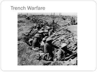
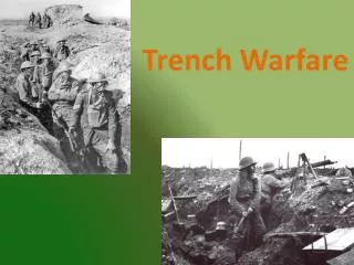
Trench Support Methods. A) Traditional Methods include the following types: i) Sheeting, waling and struts ii) Soldier piles iii) Staged trench excavation. Trench Support Methods. B) Proprietary Support Systems -

E N D
Trench Support Methods A) Traditional Methods include the following types: i) Sheeting, waling and struts ii) Soldier piles iii) Staged trench excavation
Trench Support Methods B) Proprietary Support Systems - developed by the relevant manufacturers for more labour saving construction, as well as more conscious desire for site safety. They are grouped into three broad types: i) hydraulically strutted shores and walings ii) shields and boxes iii) plate lining systems
Sheeting, walings and Struts(Fig. G-1) ..\Teaching_Notes\TEMP_WK\multimedia\Trench_SheetipilingSequence.jpg ..\Teaching_Notes\TEMP_WK\multimedia\Trench_SheetipilingSequence001.jpg ..\Teaching_Notes\TEMP_WK\multimedia\Trench_SheetipilingSequence002.jpg ..\Teaching_Notes\TEMP_WK\multimedia\Trench_SheetipilingSequence003.jpg
Sheeting, walings and Struts Materials available Sheeting: timber boards, steel trench sheets Walings: timber, steel sections, aluminium sections Struts: timber, steel trench struts(screw type), hydraulic struts, heavy duty steel struts, purpose made tubular struts
Design Methods CIRIA Report 97 (Ref.) • Use of Sheeting • Design of walings and Struts: • Either by Calculation Methods; or by Quick Reference Tables (Table G) ..\Teaching_Notes\TEMP_WK\multimedia\Trench_DesignChart.jpg ..\Teaching_Notes\TEMP_WK\multimedia\Trench_DesignChart001.jpg ..\Teaching_Notes\TEMP_WK\multimedia\Trench_DesignChart002.jpg • This method may not give the most economical solution.
Precautions in Design 1.The lateral earth pressure acting on the trench support will tend to increase with time for cohesive soils. Increased pressure should be allowed in the design for trenches which are expected to be left open for a long period
Precautions in Design 2.To avoid any weakness or excessive pressure at the cantilevered ends of the sheeting: • The first waling should be placed not lower than 500 mm below the ground surface; • The sheeting should be tied in at the base • The waling should extend approx. 300 mm beyond the last strut to ensure even spread of strut load • Timber wedges driven between waling & sheeting to ensure uniform support between the soil face and the support system
Advantages of Sheeting, Waling, Strut Support System • convenient and versatile support system • components cheap and easily obtained • light and easily dismantled by operatives • flexible to accommodate changes in trench profile, local obstruction, crossing services and construction features e.g. wider excavation for manholes • ensure safe working in all stages during hand excavation
Disadvantages of Sheeting, Waling, Strut Support System • trench walls left unsupported when full depth of the trench is excavated by backhoe/backacters • wide variations in the design ,i.e. the arrangement and spacing of struts and walings which may require attention of more competent site supervisors • Longer pipe lengths and/or plants installation may be obstructed by the closely spaced struts inside the trench of deeper depth in particular
Soldier Piles Materials 1.H-section soldier piles ( between 200x200 and 300x300 mm ), with or without timber walings and 2.the sheeting
Soldier Piles Method • H-section piles driven at 2.5 metres spacing to a depth below the trench bottom prior to trench excavation • Timber boards wedged against the inner flanges of the H-section piles or the timber walings (Fig G-2) ..\Teaching_Notes\TEMP_WK\multimedia\Cofferdam-H-piles.jpg ..\Teaching_Notes\TEMP_WK\multimedia\Cofferdam-H-piles001.jpg
Staged Trench Excavation • The excavation could be split in stages for very deep trench. • Care must be taken not to disturb the strutting of the upper stages and to allow space excavation and lowering pipes etc. between the more complex pattern of struts.
Proprietary Support Systems Hydraulically Strutted Shores and Walings Method • Most systems available are aluminium made to save weight. • The struts and palings are pre-assembled in rectangular forms which can be lowered into the trench by the excavator between previously placed sheeting ..\Teaching_Notes\TEMP_WK\multimedia\Cofferdam-Box.jpg ..\Teaching_Notes\TEMP_WK\multimedia\Cofferdam-Drag Box.jpg
Proprietary Support Systems Hydraulically Strutted Shores and Walings Method (Cont’d) • The hydraulic struts are then expanded by remote operation from ground level. • Frames up to 5 metres long walings • Struts could be used for trenches up to 5 metres wide.
Hydraulically Strutted Shores and Walings Advantages • The operatives need not enter the trench during strutting. • do not require continuous sheeting (allow gap between sheetings for crossing services)
Shields and Boxes Method • Simple two sided rectangular structures placed in the trench to provide a safe environment for operatives to work • Generally can be extended in width and height. • Sometimes the walls can be jacked Vs trench sides but for most occasions being a device to protect worker s Vs trench collapse only. ..\Teaching_Notes\TEMP_WK\multimedia\Cofferdam-Shield.jpg(Fig G-3, G-4) ..\Teaching_Notes\TEMP_WK\multimedia\Cofferdam-Box1.jpg
Shields and Boxes Advantages • The loose fit makes it easier to drag the box (by the excavator) in progress with the works along the trench.
Shields and Boxes Disadvantages • It is important to consider the loss of ground between adjacent boxes. • Do not provide significant support to trench sides • Inconvenient to use with high water tables or where services cross the line of the trench. • Weight of the box/shield could be important (could be up to 3 tonnes)
Plate Lining Systems(Fig G-5)..\Teaching_Notes\TEMP_WK\multimedia\Cofferdam-Plate-lining1.jpg Method • The system consists of rectangular plate supports with one/two adjustable struts at each end. • The plates are supplied in vertical modules to accommodate a wide range of trench depths and to enable the upper section of the trench to be supported as excavation proceeds. • Steel-made unit sized up to 5 metres long by 2.5 metres high. • Resisting external pressures up to 40 kn/sq.m.
Plate Lining Systems Disadvantages • Special care are required : • for setting out the line for the system • when dealing with crossing services and manhole positions
Working Clearances for Trench Works Trench Width (Fig G-6) ..\Teaching_Notes\TEMP_WK\multimedia\Trench_Width.jpg • to allow access for installing services, space for any sumps required, and sufficient access for compaction plant during backfilling
Safety hazards in trench excavation • Trench walls collapse ·Install trench support ·Avoid superficial load from construction vehicles • Keep stockpiling at least 1.5 m from the trench side
Safety hazards in trench excavation • Falling objects to trench operatives • Operatives to wear safety helmets • Install guard rails at both trench sides
Safety hazards in trench excavation • Misuse of lifting heavy objects by excavators ( gravity fall in case of hydraulic failure ) • Check whether the machine has been certified for lifting operations or • Use other suitable lifting plants equipped with check valves
Hazards from existing underground services • Damage live public utilities e.g. water, gas, electricity ..\Teaching_Notes\TEMP_WK\multimedia\Trench_Services.jpg(Fig G-7) • Obtain the most updated location information of the services from the relevant authorities prior to excavation
Hazards from existing underground services • Locate ferrous and power cables by electrolocation equipment • Pilot trench holes ahead of main excavations • Crossing services to be supported by hangers suspended at ground surface or propping from beneath
Hazards from existing underground services • Ground movement resulted from trench works can cause brittle cast iron pressure pipes fracture and burst (sometimes some time after reinstatement of the trench due to adjusted movement of the adjoining soil) • May require replacement of existing services by new installations through agreement with the utility authorities
Hazards to existing buildings • Deep excavation may undermine the foundations, settlement damage or collapse of adjacent buildings ..\Teaching_Notes\TEMP_WK\multimedia\Ground_Movement.jpg ..\Teaching_Notes\TEMP_WK\multimedia\Ground_Movement001.jpg
Hazards to existing buildings • Backfill the trench with concrete up to the level at which the perimeter line of the supporting wedge cuts the trench (foundation stress at a spread of 45 degrees, and additional 150 mm of concrete above the 45 degree line are assumed)
Hazards to the public at the surface • Danger to vehicles driving for carriageway trenching works • Provide properly guard rail protection (at least 1 metre above ground), traffic signs, lighting and illumination (at night) in accordance with the appropriate traffic signs design manual. • The arrangement has to be agreed with the highway authority and the police
Site Safety Regulationsfor Excavation Works Under the Contraction Sites (Safety) Regulations of Hong Kong, the Contractor carrying out excavation work shall be responsible for:
Site Safety Regulationsfor Excavation Works (1) Safety of excavation:- (a) erecting structures made by suitable material in connection with the operations of the work as soon as may be necessary after their commencement so as to prevent workmen from being endangered by a fall or displacement of earth rock or other materials adjacent to or from the side of the excavation,
Site Safety Regulationsfor Excavation Works (b) ensuring every part of the excavation to be examined by a competent person at least once per week after commencement of the excavation work until it is completed. Such a report will be made in approved forms which include a statement that further excavation is safe and secure. No further work is allowed until the report is released.
Site Safety Regulationsfor Excavation Works • (2) Fencing of excavation wherever there is risk that a person will fall a distance of more than 2 metre by: (a) erecting a suitable barrier as close as practicable to the edge of the excavation (b) the excavation is securely covered
Site Safety Regulationsfor Excavation Works • (3) No material is placed/stacked close to the edge of excavation. No load, plant is placed/moved close to the edge of excavation which is likely to cause the side of the excavation to collapse. • (4) Whenever there is apparent danger to persons employed in the excavation area from rising water or from an irruption of other material, adequate means of emergency escape must provided for such persons.
Site Safety Regulationsfor Excavation Works • ..\Teaching_Notes\TEMP_WK\multimedia\Trench_Precautions.jpg • ..\Teaching_Notes\TEMP_WK\multimedia\Trench_Precautions001.jpg • ..\Teaching_Notes\TEMP_WK\multimedia\Trench_Precautions002.jpg