Download
1 / 25
250 likes | 257 Views
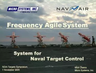
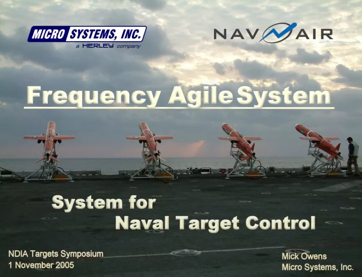
The Frequency Agile System. The Frequency Agile System Provides A New Concept for Naval Target Control: Senses RF Interference or Multipathing and Automatically Changes Frequencies To Avoid It Provides Multiple High-Speed RF Networks For Complex Target Operations

E N D
The Frequency Agile System • The Frequency Agile System Provides A New Concept for Naval Target Control: • Senses RF Interference or Multipathing and Automatically Changes Frequencies To Avoid It • Provides Multiple High-Speed RF Networks For Complex Target Operations • Compatible With Existing Ground Systems, Such As the System for Naval Target Control (SNTC)
Components Of The Frequency Agile System (FAS) Omni-Directional Antenna FAS Transponders RF Data Link 19 Channels 421.5 MHz to 448.5 MHz FAS Ground RF Unit* To Ground Control System FAS Airborne Relay* FAS Test Set* * Photographs Provide Conceptual Illustrations Of Anticipated FAS Equipment
FAS Facts • FAS Provides 200 NM Line Of Sight Distance with 12 dB of Margin • 330 NM Over The Horizon With One Relay Hop (Standard) • 730 NM Over The Horizon With Two Relay Hops (Optional) • Relay Track Information Is Provided By The Data Link • 46 16-Bit Words Are Provided In Each Uplink/Downlink Message • Includes Time, Space, Position Information (TSPI) • 9 Times More Data Than The Current SNTC, Similar To GRDCS • Selectable Uplink/Downlink Rates • Each Participant Can Have Its Own Uplink/Downlink Rate • Selectable From 1 Hz, 5 Hz, 10 Hz or 15 Hz • Uplink/Downlink Rates Remain Fixed During The Mission
More FAS Facts 4. Can Operate With 1 to 4 RF Networks Simultaneously • Example: One RF Network Could Be Used for Subscale Operations, One for Full Scale Operations, and One for Maintenance Operations 5. A Migration Path Is Provided To Satellite Command & Control • Iridium Satellite Module Is A Pre-Planned Product Improvement (P3I) • Electrical & Mechanical Interfaces Provided On All FAS Transponders 6. Can Operate In GPS-Denied Environments • Selective Availability Anti-Spoofing Module (SAASM) Is A P3I • Electrical & Mechanical Interfaces Provided On All FAS Transponders • If L2 Band Is Also Denied, TSPI Can Be Obtained From External INS
FAS Transponder System Optional Iridium Module Optional SAASM Module FAS Transponder
The Frequency Agile System Is Portable FAS can operate independently of any range or can be integrated with other range systems, such as GRDCS. This figure illustrates how the FAS could be installed and operated with GRDCS while maintaining the existing 915 MHz data link.
Goals Of The Frequency Agile System The Frequency Agile System Was Conceived During A Study Commissioned By Navy PMA-208 To Address The Following Goals For The System for Naval Target Control: • Improved Resistance To Interference • Increased Data Link Reliability • Higher Data Throughput For All Targets • Support for Complex Mission Scenarios • Low Implementation Risk • Low Implementation Cost
GOAL 1: Improved Resistance To Interference • SNTC’s 435 MHz to 450 MHz Band Is Shared • E-2C Surveillance Radars, Amateur Radio Operators, Flight Termination Systems and EPLRS/SADL • Each Of These Systems Can Interfere With SNTC • Effective Command/Telemetry Rate Can Be Affected • Can Even Stop In The Presence Of Strong Interference • Can Lead To Aborted Missions • SNTC Frequency Cannot Be Changed After Launch • If Interference Starts, There’s Nothing The SNTC Operator Can Do • One Workaround: Operate On Known “Quiet” Channels Only • But This Limits System Capabilities
Example Of Interference From E-2C An E-2C Approaches New Tx/Rx Frequency: 429.5 MHz Tx/Rx Frequency: 439.5 MHz Frequency Agile System Ground RF Unit and Antenna
FAS Frequency Scanners Each FAS Radio Has It’s Own Frequency Scanner • Each Scanner “Listens” To Each Unused Channel • Quiet Channels Are Marked As Available • The Ground System Collects Channel Data From All Transponders and Determines The Best Alternate Frequencies
The Concept Of Frequency Agility • The Frequency Agile System Is Not A Frequency Hopper • It Operates On A Single Frequency Unless Forced To Switch • Will Not Normally Switch Frequencies During Operation • Requires Severe Interference, Multipathing, or User Command • FAS Will Not Switch Into Another Problem Area • Only Switches To Pre-Scanned “Quiet” Frequencies • Won’t Switch To An Unapproved Frequency • Any Of The FAS Frequencies Can Be Blocked By Local Operators • Will Not Create Problems For Other Systems • Exploits Unused Frequencies As They Become Available • Most RF Systems Turn On and Off Throughout The Day • FAS Will Detect These Frequencies As They Become Available
How FAS Avoids Multipathing • The Frequency Agile System Detects Multipathing Two Ways: • RF Signal Degradation (Rayleigh Fading) • Multiple Data Errors With Strong RF Signal (Delay Spreading) • If Any Radio Detects Either Condition, The System Will Switch To An Alternate Frequency • Multipathing Is Very Sensitive To Frequency • Small Frequency Changes (~10 MHz) Are Very Effective
GOAL 2: Increased Data Link Reliability • SNTC Typically Operates Between 80% and 100% TQUAL • 100% TQUAL = No Missed Messages • 80% TQUAL = 20 Out Of Every 100 Downlink Messages Are Lost • Lost Messages Are Highly Undesirable for T&E • Command Dropouts Can Cause Jerky Stick Response • Telemetry Dropouts Can Result In Over-Driving The Target • T&E, Weapons Developers, and Engineering Investigations Require All Possible TM Data For Post Mission Analyses FAS Is Designed for TQUAL ³99% With 12 dB Margin • Any Scenario, Any Target • Designed For 12 dB Of Margin At Max Distance • 200 NM Max Distance With Standard Omni-Directional Antennas • 250 NM Max Distance With Semi-Directional Panel Antennas
GOAL 3: Higher Data Throughput Maximum SNTC Data Throughput (Current System): • 10 Hz Uplink/Downlink Message Rate • Maximum Rate In Direct Line Of Sight Mode • 48 Data Bits Per Uplink, 120 Data Bits Per Downlink • Throughput = (48 + 120) * 10 = 1,680 Data Bits Per Second Maximum Data Throughput For SNTC With FAS: • 15 Hz Uplink/Downlink Message Rate • Same In Direct Line of Sight OR Relay Mode • 512 Data Bits In Each Uplink and Downlink Message • Throughput = (512 + 512) * 15 = 15,360 Data Bits Per Second SNTC With FAS Can Provide Full Scale Target Control
GOAL 4: Support For Complex Mission Scenarios Maximum Capabilities For SNTC With FAS: • 8 Targets Per Frequency At 10 Hz Rate Within Line Of Sight • 4 Targets Per Frequency At 10 Hz Rate With Airborne Relay • 40 Surface Targets Per Frequency At 1 Hz Rate, Relay or LOS • Maximum of 4 Frequency Groups Per System Therefore, SNTC With FAS Can Control Up To: • 32 Subscales or Full Scales In Line Of Sight At 10 Hz • Or Up To 16 Subscales or Full Scales Through A Relay • Or Up To 160 Surface Targets Through A Relay at 1 Hz FAS Also Allows Mixed Modes of Target Types, Relays, and Uplink/Downlink Rates • Thousands of Scenarios Possible
GOAL 5: Low Implementation Risk • FAS Exploits SNTC’s “Plug ‘n Play” System Architecture • Plugs Directly Into The SNTC LAN • Installing FAS On Existing SNTC Systems Will Not Cause Down-Time • Can Be Used In Combination With Existing UHF Data Link Or Stand-Alone SNTC with UHF & FAS Data Links
Reuse of Existing Designs • Major Radio Subassemblies Have Been Previously Developed On The Navy’s Early Success Data Link (ESDL) MSTCS Program • Same Radio Is Used On FAS Transponder, GRFU, Relay & Test Set • All ESDL Subassemblies Have Already Been Qualified for Temperature, EMI, Vibration, Shock, Altitude, etc. FAS Transponder Block Diagram
Established Modulation Technique Like ESDL, FAS Uses Gaussian Minimum Shift Keying (GMSK) • Very Efficient Spectrum Usage -- Similar To SOQPSK • FAS Transmit Spectrum Shown With 265 kbps Burst Data Rate
Other Technical Details Forward Error Correction (FEC) • Detects and Corrects Errors In The Uplink and Downlink Data • IEEE 802.16a Turbo Product Codes Used For Best Efficiency 24-Bit Cyclic Redundancy Check (CRC) • Prevents Any Possibility of Erroneous Commands or Telemetry • Standard TCP/IP (Ethernet) Polynomial Multiple Transponder Interfaces • ITCS (Legacy), CDA (CANBus), and SDLC (Synchronous RS-422) Low Power Consumption • 38 Watts, Average Transponder Power
Frequency Allocation • DD Form 1494, Request for Authorization, Submitted December, 2004 • Note G8 Of The NTIA Redbook, January 2005 States: “Low Power Government Radio Control Operations Are Permitted In The Band 420 – 450 MHz” • The Navy Marine Corps Spectrum Center (NMSC) Stated Earlier: “We see no reason that this proposed modification [to SNTC] should not be approved. Particularly since it will help avoid interference situations” • NMSC Has Indicated That The Frequency Authorization (J/F 12) Will Most Likely Be Approved In Early 2006
GOAL 6: Low Implementation Cost • No New Transponder Mounting Requirements For Existing Targets • Reduced Ground Equipment Requirements • Fewer FAS GRFUs Are Needed For The Same Mission Requirements • FAS Uses Same Antennas and RF Cabling As SNTC • No New Ground or Target Antenna Installations Are Required • No Hardware Changes Required To SNTC Consoles • All FAS Ground System Functions Are Implemented In Software • Navy Does Not Lose Its Original Investment In SNTC Equipment • Target Design To Production Cost: • Same As or Less Than Current SNTC Transponder • Same As or Less Than Current SNTC GRFU