Download
1 / 67
710 likes | 939 Views
Siemens. S7-200 PLC training courses. PLC history. Classical control - More complicated - Longer time for maintenance - Time consuming troubleshooting - Occupies larger area in switchboards - Requires more wiring - Standard reliability. History.

E N D
Siemens S7-200 PLC training courses
PLC history • Classical control - More complicated - Longer time for maintenance - Time consuming troubleshooting - Occupies larger area in switchboards - Requires more wiring - Standard reliability
History • Large projects requirements -More inputs and outputs points -Large program memory -Several programming instructions -Communication with other equipments -Deal with analogue signals -Deal with large number of counters, timers and markers
History • Historical view
Course contents • Introduction to PLC • Bit logic • compare • Timers • Counters • Memory instructions • Analog I/O • Move , shift • Practical examples
Introduction • What is a PLC
Introduction • Basic PLC operation
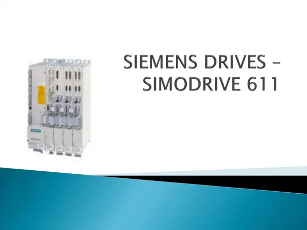
introduction • S7 200 family
introduction • S7-200 configuration
introduction • S7-200 configuration mode switch and analog adjustment
introduction • S7-200 configuration optional cartidge
Introduction • S7-200 configuration expansion modules
Introduction • S7-200 configuration status indicator
Introduction • S7-200 configuration I/O numbering
Introduction • S7-200 configuration inputs
Introduction • S7-200 configuration outputs
Introduction • S7-200 configuration programming software
Analogue I/O = Typical analogue signals from 0-10 VDC or 4-20 mA = They are used to represent changing values such as speed, temperature, weight and level
Introduction Analogue outputs may be used to produce variable reference signals for devices such as: # Control valves # Chart recorders # Electric motor drives # Pressure transducers # Analogue meters
Programming languages Ladder diagram The ladder diagram is the most popular programming language The instructions are represented by graphic symbols: Contacts, Coils & Boxes Statement list Function block
Instructions Standard instructions: They are used in most programs. Examples: timer, counter, math, logical, incr., decr. and move Special instructions: They are used to manipulate data Shift, table, conversion, real time instruction. High speed instructions: They allow for events and interrupts to occur independently of the PLC scan time. Examples: High speed counters and interrupts
Bit Logic instruction Input Instructions Normally Open contact Normally Closed contact Normally Open Immediate contact Normally Closed Immediate contact Positive Transition contact Negative Transition contact Not contact
Output instructions Output Instruction Output Immediate instruction No Operation instruction Set (N bits) instruction Reset (N bits) instruction Set Immediate (N bits) instruction Reset Immediate (N bits) instruction
Hard-wired DOL starting O.L. contact Circuit Breaker Stop Contactor Start Aux. contact Thermal Overload Contact coil Induction Motor Induction Motor
Using PLC Before start Starting After start
Timer instructions On-Delay Timer RetentiveOn-DelayTimer Off-Delay Timer
On-Delay & Retentive On-Delay timers They count time when the enabling input (IN) is ON. When the current value (Txxx) is > the preset time (PT), the timer bit is ON. The On-Delay timer current value is cleared when (IN) is OFF, while the current value of the Retentive On-Delay Timer is maintained. You can use the Retentive On-Delay Timer to accumulate time for multiple periods of the input ON.
Off-Delay timer The Off-Delay Timer is used to delay turning an output OFF for a fixed period of time after the input turns OFF. When (IN) turns ON, the timer bit turns ON immediately, and the current value is set to 0. When (IN) turns OFF, the timer counts till PT and the timer bit turns OFF and the current value stops counting. If the input is OFF for a time shorter than PT, the timer bit remains ON.
Timers numbers & resolutions Note You cannot share the same timer numbers for TOF and TON. For example, you cannot have both a TON T32 and a TOF T32.
Timer examples On-Delay Retentive On-Delay Off-Delay
Counter instructions Up counter Up/down counter Down counter A bottling machine, for example, may use a counter to count bottles into groups of six for packaging.
Up-counter It counts up on the rising edges of the Count Up (CU) input. When the current value (Cxxx) > (PV), the counter bit (Cxxx) turns on. The counter is reset when the Reset (R) input turns on.
Up/Down counter It counts up on rising edges of the Count Up (CU) input. It counts down on the rising edges of the Count Down (CD) input. When the current value (Cxxx) > (PV), the counter bit (Cxxx) turns on. The counter is reset when the Reset (R) input turns on.
Down counter It counts down from the PV on the rising edges of the (CD) input . When the current value is equal to zero, the counter bit (Cxxx) turns on. The counter resets the counter bit (Cxxx) and loads the current value with the (PV) when the load input (LD) turns on.
Counter example A counter might be used to keep track of the number of vehicles in a parking lot. As vehicles enter the lot through an entrance gate, the counter counts up. As vehicles exit the lot through an exit gate, the counter counts down. When the lot is full a sign at the entrance gate turns on indicating the lot is full.