Download
1 / 39
390 likes | 528 Views
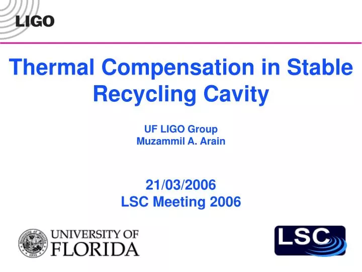
Thermal Compensation in Stable Recycling Cavity. UF LIGO Group Muzammil A. Arain. 21/03/2006 LSC Meeting 2006. Table of Contents. Stable vs. Unstable Recycling Cavities Design of Stable Recycling Cavity- Review Thermal Compensation in Advanced LIGO Design Options Substrate Compensation

E N D
Thermal Compensation in Stable Recycling Cavity UF LIGO Group Muzammil A. Arain 21/03/2006 LSC Meeting 2006
Table of Contents • Stable vs. Unstable Recycling Cavities • Design of Stable Recycling Cavity- Review • Thermal Compensation in Advanced LIGO • Design Options • Substrate Compensation • Negative dn/dT Approach • Surface Compensation • Adaptive Mode Matching in Recycling Cavity • Compensation Scheme • Experimental Demonstration • Reduced Beam Size Option • Summary
W00 V00 U00 Advanced LIGO – arm cavities • Arm Cavities: • Long and stable cavities • Uncertainties due to thermal lensing • are probably small, thanks to TCS • TCS focuses on carrier: • Optimize beam size on test masses • Optimize interferometer contrast • Optimize mode matching(?)
W00 V00 U00 Adv. LIGOMarginally Stable Recycling Cavities • Marginally stable Recycling Cavities: • All spatial modes of RF-sidebands resonant (current design: mode separation ≈ 4 kHz) • Major loss mechanism for sidebands • in TEM00-mode • Loss of up to 30%-50% • (Also for signal sidebands!) • Impact on LSC and ASC
W00 V00 U00 Adv. LIGOStable Recycling Cavities • Stable Recycling Cavities: • Only fundamental mode of RF-sidebands • resonant • Higher order modes suppressed • Strongly reduces losses of TEM00-mode • (Better performance for signal sidebands) • Expect improved LSC, ASC, and even • Bull’s eye (mode matching) signals • Interferometer will be much easier • to understand and debug
Power Recycling CavityCold State ITMy PR1 PR2 From MC ITMx PR3
Hot Operation @ 120 W 6 cm Beam Size and 0.5 ppm Loss in ITM 110 km Thermal Lens at Surface 6.8 km Thermal Lens in Substrate
Thermal Lensing in ITM Surface Deformation (64.76 km Thermal Lens, 12 th Degree Polynomial Fit to H-Vinet Theory)
Thermal Lensing in Substrate Thermal Aberrations (12 th Degree Polynomial Fit to H-Vinet Theory)
s(x) x E1(x,z) E2(x,z) wo R(z) R1 Optimized Thermal ROC Estimation Calculate Overlap Integral b/w E2 and E3 and maximize it w.r.t. the ROC of thermal lens to get the optimal value
The Solution An analytical solution is difficult however a numerical solution can be obtained. The curve is a parabola like shape and the vertex gives you the optimal value. Solution: Numerical Integration
Comparison of ROC Change Estimation Thermal Lens in ITM Thermal Lens in Substrate
Hot Operation @ 120 W Other Options 1. Reduce Beam Sizes to 5.5 cm → Higher Noise 2. Move Telescope into arms → Space Restrictions 6 cm Beam Size and 0.5 ppm Loss in ITM 110 km Thermal Lens at Surface 6.8 km Thermal Lens in Substrate Com. Plate ? 15% Losses in RC No Adaptive Mode Matching End? 96% Mode Matching No Yes Yes End ? Option 3 Option2 Option1 RH & Adaptive Telescope Adaptive Telescope On PR2 and PR3 Ring Heater On ITMs Advantages: 1. 100% Mode Match 2. No Differential Effects Disadvantage 1. Relatively large power 2. Induced Noise Advantages: 1. 100% Mode Match 2. Insensitive Optics 3. Non-power-related mismatch Disadvantage 1. Only Common Mode Corr Diff. through RH Common through PR2 & PR3 Advantages: 1. 100% Mode Match 2. Low RH Power 3. Low Noise Induction
Annular & Ring Heater Compensation Increasing Value +ve dn/dT Plate (Fused Silica) Probe Beam Constant Power Plate acts as a diverging lens Annular Heating Beam Refractive Index is decreasing at the center Annular Heating +ve dn/dT Plate (Fused Silica) Probe Beam Constant Power Plate acts as a diverging lens Ring Heaters Increasing Electrical Power Refractive Index is decreasing at the center Ring Heating
Negative dn/dT Compensation Constant temperature, Uniform refractive index Increasing Value Normal Divergence Probe Beam (1064 nm) Low power Negative dn/DT plate Plate acts as a simple glass plate Refractive Index is decreasing at the center Plate acts as a diverging lens Probe Beam (1064 nm) Increasing Power Passive Compensation Plate acts as a diverging lens Probe Beam Constant Power Active Compensation Heating Beam
Active Compensation Requirements: CO2 laser system for surface heating Availability in Large Size Purity/homogeneity Advantages: Works without any doubt, trick is use same beam size as ITM Requires very low power (< 2W) Highly Efficient/Adaptive Disadvantages: New material A lot of Data and tests needed Requires coating on both surfaces Passive Compensation Requirements: Availability in Large Size Purity/homogeneity Exact Size absorption values Advantages: No laser needed Highly Efficient Analogous to compensation in Faraday Rotator Disadvantages: New material A lot of Data and tests needed Less Adaptive Requires coating on both sides Option 1: Negative dn/dT Does such a material Exists ?? Combination of Two is essential due to substrate heating at 1064 nm
Potassium Bromide, Initial Choice • Important Properties (KBr): • n = 1.5441 @ 1064 nm • (dn/dT-(n-1)at = -17.43×10⁻⁶ /0C • Absorption = 0.002 cm-1 • Kt = 4.816 W m-1 K-1 @ 319K • Normally used in IR Spectrometers • Available in large sizes • Crystalline in nature • Soluble in water • Important Properties (Fused Silica): • n = 1.4497 @ 1064 nm • dn/dT = 8.7×10⁻⁶ /0C • at = 5.5 ×10⁻⁷ /0C • Absorption = 2 ×10⁻⁶ cm-1 • Kt = 1.37 W m-1 K-1
A Typical Example6.42 km Thermal Lens in Substrate • Crystal Thickness = 2.05 mm • Coating Absorption = 2.0 W • Uncompensated Losses = 11% • After Compensation = 0.001%
Option 2: Ring Heaters General Comments Easy to control electrical power Sensitive to geometry Requires relatively high power Compensating a lens of 6.8 km in substrate might be too much for ring heaters Increases the temperature Further Considerations for Experts Annular Heating General Comments Established technique Probably will require less power as compared to Ring Heaters Silica can be used as compensation plates No new material is required Still needs an extra laser and related control like negative dn/dT Less efficient than negative dn/dT method Other Options for Compensation
Surface Thermal Lensing 1. Highly variable due to coating variations2. Differential Variations can be severe3. Changes the mode in the arm cavity and mode matching can decrease to 96% without correction4. Can cause contrast defects
Adaptive Mode Matching Recall: RH & Adaptive Telescope Adaptive Telescope On PR2 and PR3 Ring Heater On ITMs Advantages: 1. 100% Mode Match 2. No Differential Effects Disadvantage 1. Relatively large power 2. Induced Noise Advantages: 1. 100% Mode Match 2. Insensitive Optics 3. Non-power-related mismatch Disadvantage 1. Only Common Mode Corr Diff. through RH Common through PR2 & PR3 Advantages: 1. 100% Mode Match 2. Low RH Power 3. Low Noise Induction Proposed Scheme Procedure 1. Use RH on ITMs to keep the ROC on both ITMs same. 2. Use Adaptive correction on PR2 and PR3. Assumptions 1. We have selected a base value of 0.5 ppm as coating absorption 2. Any deviation more than this, has to be corrected by RH. (Probably requires very low power). 3. If absorption is low, we have to apply some correction in the hot case.
Compensation Scheme for Adaptive Mode Matching – Hot Case ITMy RH COMy Optional RH CO2 Laser Beam PR1 PR2 Optional RH RH From MC ITMx PR3 COMx CO2 Laser Beam PR2 and PR3 ROC designed for hot value with 110 km thermal lens at ITM surface (i.e., 0.5 ppm, ITM ROC 2076 m)
Compensation Scheme for Adaptive Mode Matching- Cold Case ITMy RH COMy CO2 Laser Beam PR1 PR2 From MC ITMx PR3 COMx
Correction @ PR2 Requires a 10 m converging lens at 3.5 mm as we move from hot to cold case Easily achievable by using CO2 heating Experimental demonstration in progress Correction @ PR3 Requires a 3.4 km diverging lens at 7.1 cm beam size as we move from cold to hot case Proposed locations are substrate of PR3 or separate plate before beam splitter No higher order losses in the hot state 10% higher order losses in the cold state Cold state losses can be decreased by using CO2 beam of larger size Details of Adaptive CorrectionPR Cavity Designed for Hot Case BS Substrate Lens Heating Plate Heating
1 cm Thick Fused Silica Plate 1.8 mm Probe Beam HR Coating @ 1 micron 1 cm CO2 Heating Beam Experimental Demonstration Summary • Solid Line is H-V Theory • Dots are experimental data • 10 m focal length lens at 1.2 W of surface heating at 1.8 mm probe beam and 1.0 cm heating beam
Problems/Concerns • CO2 beam power stability • ‘Beam Walking’ Problem • Beam Pointing Stability • Geometrical Considerations
Inherently ‘Athermal’ Cavity Reduce the Beam Size Increase the ROC
Reduced beam Size Operation Can we operate here ??? • No Correction Required • Thermally Stable • No differential problems • Increased Noise • Reduces Sensitivity • Deviates from 6.0 cm magical beam size value ??
Thermally Insensitive Operation at Reduced Beam Size Arbitrary Limit of 99% Mode Matching • Hot ROC = 2137 m, Cold ROC = 2096.27m • Beam Size = 5.7 cm • No Correction Required • More Stable
Thermal Noise Considerations 1. Thermoelastic noise scales as 1/(beam size)3/2 , not thermal noise 2. Thermoelastic noise is a minor contributor to the total thermal noise 3. Total Noise does not scale as 1/(beam size)3/2 of beam size
Comparison of Total Noise Maximum hit of 4.5 % at 64 Hz Is it acceptable??
5.7 cm Beam Size Details: Finesse: 1238.07 Power Recycling Factor: 16.83 Power on beam splitter: 2019.75 NS Binary Inspiral range: 126.24 Mpc Stochastic signal sensitivity: 6.836e-009/h^2 6.0 cm Beam Size Details: Finesse: 1238.07 Power Recycling Factor: 16.83 Power on beam splitter: 2019.75 NS Binary Inspiral range: 130.61 Mpc Stochastic signal sensitivity: 6.682e-009/h^2 Familiar Bench Noise Curve Hardly any difference in Log Scale Can we sacrifice a little sensitivity ??
Summary/Recommendations 6 cm Beam Size and 0.5 ppm Loss in ITM 1. Reduce Beam Sizes to 5.7 cm → Higher Noise 110 km Thermal Lens at Surface 6.8 km Thermal Lens in Substrate Recommendation Suggestions Comments Com. Plate ? Adaptive Mode Matching Yes Option 3 RH & Adaptive Telescope -ve dn/dt Material Plate Diff. through RH Common through PR2 & PR3 Advantages: 1. 100% Mode Match 2. Low RH Power 3. Low Noise Induction