Download
1 / 152
1.54k likes | 1.66k Views
EO-1 Spacecraft Bus Initial Early Orbit Checkout (IOC) Review December 14 th , 2000. Swales Aerospace. Review Overview. Michael J. Cully EO-1 Program Manager, Swales Aerospace. Agenda. Overview ……………………………………………………………….. Michael Cully

E N D
EO-1 Spacecraft Bus Initial Early Orbit Checkout (IOC) Review December 14th, 2000 Swales Aerospace
Review Overview Michael J. Cully EO-1 Program Manager, Swales Aerospace
Agenda • Overview………………………………………………………………..Michael Cully • Chronology of Spacecraft Bus Checkout………………………...Mark Perry • Systems Engineering Performance………………………………..Mark Perry • Electrical Systems…………………………………………………….Bruce Zink • Mechanical Systems………………………………………………….Pete Alea • Attitude Control Subsystem………………………………………...Paul Sanneman....……………………………………...Dave Speer…….…...……………………………...Kathie Blackman • Reaction Control Subsystem………………………………………. Michael McCullough • Power Subsystem……………………………………………………. Al Billings…………………………………………………….Ralph Sullivan • Thermal Subsystem…………………………………………………..Nick Teti • Communications Subsystem……………………………………….Tom Spangler (GSFC Support) • Command and Data Handling……………………………………… Steve Schumacher (GSFC Support) • Flight Software………………………………………………………...Gary Smith • Management Wrap-Up………………………………………………..Michael Cully
Scope of Review • Provide Initial On-Orbit Performance of Subsystems • Provide details of any anomalies or problems • Provide GSFC Flight Director & Operations Team with list of Major changes to operations as a result of initial on-orbit performance • Nominal configuration changes since launch, and new operational alerts or constraints • Revised limits • Deleted commands (commands that are no longer necessary) • Revised calibration parameters • Provide Lessons Learned to GSFC to improve future missions in same class • Address lessons learned from major Problem Reports • What did we do right that made EO-1 a success!
Systems Status Mark Perry EO-1 Spacecraft Systems Engineer, Swales Aerospace
Overview of EO-1 On-Orbit Performance • The EO-1 spacecraft is “hugely successful” • Nearly flawless during deployment, early orbit, and normal operations • Fully tested, except for PPT firing, the lunar raster scan for calibration, and some Fault Detection and Correction (FDC) that we do not intend to test • 3 known hardware or software anomalies (only one s/c anomaly) • Intermittent GPS drop-outs: understood, mitigated by simple table load • Hyperion-to-ALI misalignment: Hyperion FOV not entirely within ALI FOV • One LFSA temperature sensor failed. LFSA technology already evaluated • Two areas of disappointing performance • AST loses track at ~60 degrees to sun rather than ~30 degrees: no effect on normal operations • Oscillations in s-band: mitigated by large margins • Many areas perform better than required and expected. Some examples (details in subsystem presentations): • ACS stability during images has been measured better than the goal • S-band uplink/downlink margin is more than 25 dB higher than budgeted! • Command and ground station errors caused anomalous conditions • The s/c team recovered each incident quickly, without problems
FDC/TSMs • Safe-hold and load-shedding successfully tested (see ACS presentation) • Several TSMs (M5-controlled FDC) tripped due to anomalous conditions precipitated by command errors • All TSMs functioned as expected • All unplanned events corrected without adverse effect on EO-1 • Several ACS FDC checks tripped • Some due to anomalous configurations or conditions, others due to expected conditions • All FDC trips are understood • All FDC and TSMs tested before launch
Pre-Launch Testing and Training • EO-1 operational success attributed in part to extensive test and simulations • Five comprehensive performance tests • More than five two-day simulations than included contingencies • Second thermal-vacuum test • S/C engineering team and FOT fully prepared before launch • Extensive documentation: S/C User’s Guide, Pre-Launch and Early-Orbit Handbooks, Contingency Flow Charts • Contingency trees reviewed and contingency procedures tested
Changes to Flight Software, Database, and Limits • Software modifications described in subsystem presentations • Some modifications to optimize performance (e.g., some ACS alignment parameters) • Some adjustments to FDC trip points based on on-orbit experience • Many changes to EO-1 operations based on experience to date • Changes to procedures, planning system, constraints, and limits • Improve old RTSs and add new RTSs to increase efficiency and to correct errors that created anomalous conditions • Changes captured in Database Change Requests and approved by the EO-1 CCB
Lessons Learned • Two lessons from late avionics: • Development projects take more time than COTS. The ACDS, PSE, C&DH S/W, and 1773 transceivers did not meet schedule. • ETUs are needed. They save time, schedule, and resources • Lots of test time is good. At both the box level and at the satellite level. This includes launch and orbit simulations. • The minimum set of necessary documentation is not zero • Needed C&T handbook prior to start of I&T • Needed additional documentation on engineering decisions • You cannot force 6 months of I&T into two months • An aggressive schedule that does not contain contingency time is only viable for well-tested components, that is, for repeated tests or integration
Electrical Systems Bruce Zink EO-1 Electrical Systems Lead, Swales Aerospace
Agenda • Electrical Systems Performance • Anomalies / Unexpected Events • Configuration Changes since Launch • Lessons Learned
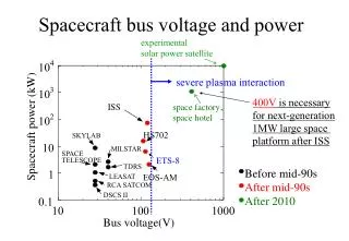
Electrical Systems Performance • 1773 Data bus performing flawlessly • No SEU’s • No data corruption • No harnessing issues • Power distribution nominal • Internal data communication nominal (wrt wiring) • Power system nominal • Solar array deployed on schedule and performing within predictions • Power balance following predictions • Early operations put peak loads on power bus causing some bus voltage issues • Off pointing array due to burns and slews causes brief balance issues, which are recovered within one orbit (typically) • Battery performing nominally • Battery age possibly showing up in EON voltages as battery “breaks in” • Bus voltage within acceptable parameters (modified expected values to reflect battery performance)
Electrical Systems Performance (CONTINUED) • RF S-Band communications nominal • See Comm presentation for details • RF X-Band communications still in checkout • Ground station / Spacecraft interaction still being explored with respect to NMP XBPAA • C&DH subsystem performing nominally • Single bit errors occurring in memory (assumed due to SEU’s) • Memory scrub task rate increased to compensate • CPU utilization with respect to EFF still to be determined • GPS interface SW issues (see ACS and Flight SW sections) • LFSA deployed successfully and data collection taking place • Performance within predictions of manufacturer • One thermistor (of two) has gone “open circuit” following several days of operation • Thermistor’s “bottom out” at -36C (capability of spacecraft acquisition system)
Anomalies / Unexpected Events • LFSA deployment caused S/A to go to index • TSM’s (71 and 72) for separation and deployment tripped when launch packet enabled • TSM’s accidentally enabled prior to LFSA deployment • Caused S/A to go to index (part of launch sequence RTS 34) • Re-enabled S/A tracking on next command pass. Disabled relevant TSM’s. Disabled launch packet. • Yoke (deploy) hinge pot drifted from 99% following deployment (day 326) to 94.7% (day 331) • No indication of actual movement on S/A power output (cosine function would preclude measurement) • No indication of any other telemetry points using same current source and A/D drifting • Total change was 9 A/D counts (or 45mV) • Potentiometer settling and A/D “misbehavior” suspected as cause • No action required
Anomalies / Unexpected Events (CONTINUED) • LFSA thermistor “open circuit” • Following several days of operation one of the LFSA panel thermistors “stuck” at -36C, indicating an open circuit condition • Previous to failure both thermistors “bottomed out” at -36C, which is the minimum temperature measurement of the sampling system • Cold end predictions of LFSA exceed manufacturers specifications • Most likely thermal stress (see thermal presentation)
Configuration Changes since Launch • None in Electrical Systems
Lessons Learned • Nadir Deck Heater Short (discovered in TVAC 1) • Wire lists should be used for complex circuits instead of schematics • Circuits should be tested exactly as expected in flight • Cable Wrap Wiring Damage • Identify “at risk” harnessing and protect it! • Implement “spares” in areas which cannot be supplemented (done in cable wrap as part of design) • Keep margin in all areas to accommodate potential repairs
Lessons Learned (CONTINUED) • EGSE “robustness” • Build EGSE to withstand travel and extended use (spend your time up front) • Equipment racks • Cabling • Do not let “quirks” of EGSE performance to propagate too long following discovery • Umbilical GPIB • APTS to ASIST link • ETU’s / FLATSAT • Build and use necessary ETU’s early • Minimize “development” on flight hardware • Integrate complex interfaces early as they are identified
Mechanical System Pete Alea EO-1 Mechanical Systems Lead, Swales Aerospace
Agenda • Satellite Launch Configuration • Final Mass Properties • System Tests Performed • Mechanical System Performance • Lessons Learned
Satellite Launch Configuration EO-1 Nadir View EO-1 View From Bay 2/3
Satellite Launch Configuration • There were no open PRs or deviations to the nominal satellite mechanical flight configuration at launch • Most red tag items were closed out at Astrotech or SLC-2 prior to fairing installation • The A/C vent and purge line c/o was completed during fairing finalization A/C Vent Closeout Purge Closeout
EO-1 Mass Growth Final EO-1 Mass at Launch was 566 Kgs, 22 Kgs under allocation of 588 Kgs!
System Tests • The following Satellite level environmental tests were performed: • Modal Test, 7/1999 • Shock Test, 8/1999 • Vibration Test, 8/1999 • Acoustic Test, 8/1999 • Mass Properties, 9/2000 • For all tests, the primary objectives were successfully achieved without any observed failures • Retesting of the satellite system was not required after reworking the WARP, ACDS and S-Band avionics due to the proven integration process used
Mechanical System Performance • Final launch loads should be enveloped by the VLA • Final report to be provided by Boeing for Delta 282 Mission
Mechanical System Performance • Solar array deployment observed from telemetry data: • HOPAs Powered Up at 326-19:24:25.3 • Solar Array Release at 326-19:27:16.8 • Nominal Time Expected from Ground Deployments 3 mins • Actual Time 2 mins 51 secs • HOPA Performance Nominal ! • Full Deployment at 326-19:28:24.6 • Nominal Time Predicted 90 secs • Actual Time 68 secs • Deployment time somewhat less then predicted from kinematics model due to effects from S/C tumbling
Lessons Learned • A Gr/E composite structure would have been lighter weight then our baseline aluminum structure, however, for a technology driven satellite like EO-1, there are undesirable limitations imposed by a Gr/E structure: • The addition of the Hyperion Instrument could have compromised the existing Gr/E S/C structure. The Al structure was far more forgiving and easier to interface. • The addition of last minute components such as the AST TSA and WARP Filter Box would have been difficult and costly to implement • Damage tolerance is far greater with an Al structure then Gr/E. De-integration and re-integration subsystems would have been more time consuming with Gr/E structure and panels. • The mass allocation was adequate for the aluminum structure
Lessons Learned (CONTINUED) • Minimizing the existing S/C interior volume is undesirable for new technology satellite • Addition of unforeseen components would not have been possible (fuse plugs, SADA rework bracket, filter box,..) • Re-integration of avionics would have been far more difficult without the addition of the GSE hinges • Even thorough the S/C interfaces were planned into the structure early on, the actual hinge design and fab were not approved until after Hyperion was added to the program • Requirements for all GSE hardware need to be clearly defined during the initial program study phase and revisited when program changes are made
Lessons Learned (CONTINUED) • The EO-1 environmental specification should included guidelines for testing reworked hardware to streamline the decision making process. Similar guidelines should also exist in the GSFC GEVS document. • Spacecraft deintegration/reintegration activities required the repeat or performance of all alignment measurements six weeks before launch • Future efforts should provide adequate time for both the acquisition and processing of instrument and spacecraft metrology data • We were partially prepared with spare wires for the solar array cable wrap damage • The termination of the spare cable wrap wires could have been placed in a more effective location to play a greater role in solving the problem • Spacecraft harnesses which are susceptible to damage or difficult to repair/rework should be protected during all phases of I&T
Good Lessons Learned • Mechanical design team staffing was appropriate. Small group in a “Skunk Works” type environment. Corporate support was consistent with final result. • Direct fabrication of primary structure components from Pro/E database worked well for decks and radials to reduce design/manufacturing cost. Not as effective for mechanism components were interface checks must be performed with detail drawings. • Manufacturing tool design and fab should be worked in parallel with final phase of flight hardware design to minimize fab schedules • One mechanical team following the hardware from “Cradle to Grave” works well for EO-1 type program. This approach allows for quick response to issues that come up during I&T.
Good Lessons Learned (CONTINUED) • EO-1 success was due to a team of individuals from all aspects of the Swales’ including engineering, purchasing, receiving and manufacturing. Bring everyone into the “Team” was key to our success.
Attitude Control Subsystem Paul Sannenman EO-1 ACS Systems Lead, Swales Aerospace Kathie Blackman Jeff D’Agostino Teresa Hunt Dave Speer Seth Shulman
ACS Summary • Initial Acquisition Performance Summary • Attitude Control Electronics • AST Performance • IRU PDV Trend • Attitude Determination - Kalman Filter & Alignment • Magnetic Calibration Results • ACS Flight Software • ACS FDC Trips • ACE Safe Hold Mode Test • Delta-V Attitude Control Performance • Science Pointing Accuracy Assessment • Anomalies • Lessons Learned Summary
Initial Acquisition Performance 00-326 • Separation Rates[3.61, 0.42, -0.19] deg/sec • Angular Rates after Solar Array Deployment [1.11, 1.72, 1.0] deg/sec • Bdot Magnetic despinDuration of 78 minutes • Initial Sun Acquisition • Initiated at 20:42 just prior to orbital eclipse period • Performed angular rate damping and RWA momentum dumping during eclipse • Initiated pitch flip after entering into orbital day • Completed at 22:00 • RWA Momentum UnloadCompleted by 23:00 Angular Body Rates in Arcsec/sec
Attitude Control Electronics • Overall operation of Attitude Control Electronics has been nominal • No observed anomalies in power supply voltages, ACE total current, or calibration/reference signals (but much more analysis to be done). ACE card temperatures very comfortable in +25°C to +35°C range. A-to-D converter on ACE RSN card still skipping codes (known issue). • All ACS component power, command, data and telemetry signal interfaces being continuously exercised and working as expected, including CSS’s, TAM, MTB’s, IRU, AST and RWA’s. Subset of PPT signals are working, but PPT Fuel Gauge 1 signal is very noisy (known issue) and PPT charge/fire commands not used. • Solar Array Drive systems working very well after 300+ track/rewind cycles. Redundant drive verified briefly during Safe-Hold test, & secondary encoders turned on & used for two orbits (then turned back off). • RCS/Propulsion system function was excellent during the first 6 delta-V maneuvers, but analog current sum signal hard to use due to heating • No SEU’s observed in digital electronics (including FPGA’s) after 500+ hours in space and 100+ passages through South Atlantic Anomaly • Comprehensive analysis and trending of ACE signals and parameters planned for the written report (and after DTAS upgrades)
AST Performance • Overall Autonomous Star Tracker performance has been excellent • Tracking from 14 to 40 stars, all initial attitude acquisitions successful • RMS error based on AST calculations ~ 10 to 15 arcsec • Ground processing indicates approximately 30 arcsec, 3-sigma • At least two occasions of RMS error spikes under investigation • Effective Focal Length indicates <10 um error - no update needed • Baffle protection • Earth Limb: 6 to 18 degrees depending on Earth illumination • Moon: 12 to 15 degrees • Sun: 65 degrees ( 3 occurrences) - • Expected 20-30 degrees • Other LMMS AST baffles have also exhibited less protection than specification • Impact to mission planning and expect to update ACS Table • No Reboots while in the SAA • 00-345 anomaly near south pole caused AST to enter STANDBY mode • Several transitions to COAST mode without loss of Track
IRU Performance • PDV Trends still improving - no sign of helium exposure on launch pad • Initial calibration of gyros based on 00-328 Gyro cal maneuvers • Estimated IRU Drift Biases of[1.02 0.08 1.58] deg/hr in [X,Y,Z] • Most important, these values have remained constant • [1.0 0.0 1.5] deg/hr in [X,Y,Z] on 00-347 from ACS Kalman Filter • Calibration identified negligible scale factor error • IRU-to-AST on-orbit alignment calibration resulted in less than 0.2 degree (720 arcsec) change
GPS Performance • Two cold start acquisitions in Sun Pointing orientation • Remained in track “POS FIX IN PROC” during all gyro cal slews, Delta-V slews and imaging slews • Started GPS updates to ACS on 00-329 16:55 after two days monitoring the performance compared to ACS propagated and ground solution • Navigation vectors (S/C position and velocity) performance has been well within specification - within 100 meters • GPS data interface to HK RSN has encountered some outages due to packet validation algorithm and data format anomalies • Some are predictable at this point, while others are still being investigated • Tuesday night issues due to A1 (hex) packet ‘milliseconds into week’ • 00-334 02:37 65 second outage caused drop in ACS processing • 00-341 00:14 Longer outage due to packet 41 (hex) data values corrupting the packet recognition algorithm in the HKRSN in conjunction with the A1 (hex) packet ‘milliseconds into week’
Attitude Determination • Kalman Filter operations commenced Day 1 • Slew maneuver performance not as expected starting with first EarthAcq • AST alignment update based on alignment cube measurements • 3+ deg offset from ALI based on cubes - not valid; restored original • Decided to keep to plan for using IRU alignment calibration results • Continue to operate in ‘Not Converged’ state • Misnomer for residual error tolerance limit (multiplier) • Updated value from ~40 to ~450 arcsec tolerance on day 340 17:04 • IRU alignment matrix updated on 00-339 21:01 • Problems during slews prior to science images and delta-v burns • Affected both Delta-V and imaging DCE accuracy ~ 1 Deg • Kalman filter tuning analyses underway • Will result in update to KF noise parameters to effectively reduce gain associated with IRU drift bias estimation • FDC Test 79, Kalman Filter divergence test, has tripped more than once • Currently disabling test when AST updates not available for extended period, such as Earth/Sun occultation, anomalies, etc • Will no longer be necessary once KF tuning update is completed
Magnetic Calibration • Day 1 FDC test 75,76,77 trips indicated some magnetic field issues • FDC Test 5 Trip after Inclination Delta-V was a surprise and caused transition to SunAcq mode • S/C Residual dipole creates [-1.53 1.02 -1.32 ] uTesla field at TAM • Static compensation values updated on 00-332 (ACS Table 57) • MTB-to-TAM compensation matrix updated based upon on-orbit data • I&T data known to have some corruption due to facility issues I.e. REE-bar in flooring and clean-tent structure • Compensation matrix values updated on 00-332 (ACS Table 67) • At full MTB dipoles, the miscompensation was near 5 uTesla • Based on this calibration, ground-based attitude determination software using TAM and gyro data is providing better than 1.0 deg accuracy
ACS Flight Software • M5 ACS FSW performing nominally • All control modes except Science Imaging Mode have been exercised • No plan to use Science Imaging Mode on-orbit • Science Imaging Mode uses same controller as Mission Idle Mode • No code patches have been implemented on ACS FSW • One patch developed (Replace IRU rate data with AST rate data) before launch • Not needed • One patch is under development (algorithm correction for Yaw Steering capability) • Yaw Steering is currently disabled and not required
ACS Flight Software Tables • Five ACS tables modified prior to launch • ACS table modifications since launch: • #65 (AST Alignment) on 00-327 to correct possible misalignment; restored from EEPROM on 00-328 (correction not needed) • #57 (TAM Parameters) on 00-332 to help reduce FDC trips • #58 (TAM Transformation) on 00-332 to help reduce FDC trips • #67 (TAM Contamination) on 00-332 to help reduce FDC trips • #56 (IRU Transformation) on 00-339 to improve Kalman Filter attitude and gyro bias estimation accuracy • #73 (Thruster Parameters) multiple times to modify max burn time; restored from EEPROM after each Delta-V • #85 (Ephemeris Limits) on 00-346 to widen “bad GPS” timeout • Pending ACS table modifications • #90 (Control Mode Configuration) and #97 (ACS RTS List) under investigation for possible addition of RTS upon Sun Acquire mode entry • #61 (Coarse Sun Sensor Parameters) to update for peak output value • #76 (Solar Array Control Parameters) to improve track acquisition rate • #64 (Star Tracker Parameters) AST/Sun Interference Angle and AST/IRU FDC Rate Limits
ACS FDC Trips • Tests 75,76,77,5 - due to magnetics • Tests 1 due to pitch slew rates and AST Z-axis rate accuracy • Test 79 KF divergence • Test 24 (GPS Data Invalid) was disabled during 00-341 long-term outage • Plan to re-enable pending resolution of long-term outage issue • Test 6, 7 and 8 MTB Dipole Cmd vs Measured during SHM • Need to disable FDC during SHM • Test 84 HW/SW Eclipse mismatch due to CSS normalization issue • Test 64 Disabled for Delta-V on 00-346 due to duration > 1000 sec • Re-enabled after Delta-V
ACE Safe Hold Mode Test 00-327 • Safe Hold Mode control test included as part of Day 2 activities • Ground commanded entry via same method as fault trip - RTS 2 • Load shed commands all executed, but many services had not yet been ON • Excellent attitude control performance for Sun Pointing the solar array • Spec of 25 deg, 3-sigma • Performance 3-5 deg, 3-sigma, including CSS albedo errors • Autonomous switch to redundant side of SAD/ECU and drive to Index successfully demonstrated • SHM Recovery procedure validated SHM Control
MissionDay 4 6 8 10 19 21 23 25 25 UTCDay 00-329 00-331 00-333 00-335 00-344 00-346 00-348 00-350 00-350 UTCStart 15:19:39 13:49:04 15:03:09 14:10:09 13:24:14 03:36:37 14:08:09 Dur.Sec 60 514 831 901 430 1015 75 BurnType ALT+ INC ALT+ ALT+ ALT-- ALT-- INC Delta-Vm/sec 0.21 1.81 2.71 2.77 1.32 2.83 Fuelkg 0.058 0.491 0.735 0.743 0.342 0.759 Error% DV +1.0 +1.4 +0.11 +1.4 -1.0 +1.1 Delta-V Performance • Attitude control performance during thruster-based delta-v mode has been excellent • Phase plane plots indicate expected trajectories • Attitude errors have steady-state values near [1.6 -1.0 0.0] deg, XYZ • Indicates very good correlation between RCS fab/test, mechanical mass properties tracking and ACS controller design
Science Pointing Accuracy Assessment • Attitude Control [30, 30, 30] arcsec, 3-sigma budget allocation • X & Z consistently under 30 arcsec, Y varies 0 to 50 arcsec depending on settling time • Attitude Knowledge [54, 108, 54] arcsec, 3-sigma budget allocation • All axes consistently under 36 arcsec, 3-sigma during normal nadir-pointed operations • Navigation Accuracy [130 m Cross-Track, 100 m Along Track] 3-sigma • Cross-track 45 m, 3-s; Along-Track, 55m 3-s; Radial, 30 m, 3-s • Jitter/Rate Stability • Better than 0.5 arcsec/sec, 3-sigma during imaging • RWA Zero Speed crossings • [45,120,35] arcsec peak transient with 2 minute width • Thermal Snap transients • 40 to 80 arcsec peak transient per axis with 2 minute width • ALI Cover open transient • 300 arcsec peak transient in pitch axis - zero’d within 2 minute prior toDCE at 3 minutes (even when RWAs are biased near 1000 RPM asevidenced by 00-347 Cape Canaveral DCE)
ACS Anomalies • AST alignment based on optical cube data was not accurate • Kalman Filter performance during attitude slew accelerations • Need to modify gains to improve IRU Drift Bias estimation accuracy • Should also prevent FDC Test 79 trips due to KF divergence • FDC Test 5 trip caused transition to SunAcq - MTB-to-TAM coupling issue • GPS data interface to HKRSN experiencing outages • A1 Packet ‘milliseconds into week’ causes Tuesday Night outage • AST sun separation protection from baffle only 65 deg not 30 deg • AST transition to STANDBY on 00-345 15:04 - expect SEU