Download
1 / 15
150 likes | 288 Views
2.5 MHz Acceleration in the Main Injector Vincent Wu and Chandra Bhat Brian Chase and Keith Meisner (LLRF group) Jim MacLachlan 2/26/2003. 1. Simulation - space charge and beam loading 2. Implementation of 2.5 MHz Acceleration 3. Future work. Simulation of 2.5 MHz Acceleration.

E N D
2.5 MHz Acceleration in the Main InjectorVincent Wu and Chandra BhatBrian Chase and Keith Meisner (LLRF group)Jim MacLachlan2/26/2003 1. Simulation - space charge and beam loading 2. Implementation of 2.5 MHz Acceleration 3. Future work
Simulation of 2.5 MHz Acceleration Initial beam and rf parameters: - total beam energy (GeV): 8.938 - momentum compaction factor: -0.008683 - rf frequency (MHz): 2.5 - rf voltage for 2.5 MHz rf system (kV): 2 - invariant 95% longitudinal emittance (eVs): 1.5 per bunch - number of particles per bunch: 6E10
Simulation with Space Charge and Wall Impedance Input parameters: - assume circular beam pipe with 1.7 GHz cutoff frequency - Z11/n: 1.6, 3.2, 4.8, 6.4, 8 - 1.6 is the “measured” MI longitudinal impedance per harmonic - number of macroparticle: 200000 - single bunch (6E10)
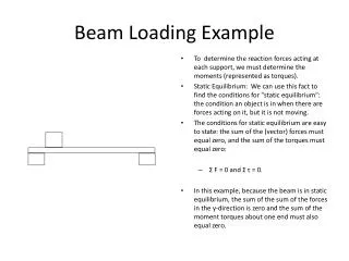
Simulation with 2.5 MHz Beam Loading • 4 bunches and 1 cavity • Cavity Q=112.5 and Rsh=45000 Ohm • To simulate 5 cavity beam loading, the shunt impedance is increased by a factor of 5. • Results • Peak beam loading voltage: 1.9 kV • At beginning of 27 GeV rotation, beam loading • voltage is 1.4 kV and cavity voltage is 1 kV. • Overall emittance grow is problematic. • Conclusion: need 2.5 MHz beam loading • compensation.
2.5 MHz Acceleration • Tune transverse motion using 53 MHz bunches, i.e., fine tune chromaticity and tune programs to obtain good transmission. • Try open loop 2.5 MHz acceleration while the radial and phase feedbacks are being worked on. -- 4 Booster batches injection with 7 bunches per batch. -- 53 MHz bunches are adiabatically debunched into 2.5 MHz buckets.
Beam Loss Bottom plot: Radial position of 2.5 MHz beam (bottom curve) and phase of the beam (upper curve).
Transverse Emittance During 2.5 MHz Acceleration At 9 GeV: vert.emit=10.4, hor.emit=10.7 At 19 GeV: vert.emit=12.2, hor.emit=10.3
Longitudinal Emittance 53 MHz bunches at injection, first batch Average emit. per bunch=0.19 eVs Total emit. = 1.6 eVs
2.5 Mhz bunches at 8 GeV before acceleration Emit. for first bunch = 2.4 eVs
2.5 MHz bunches at 19 GeV before transition Emittance of first bunch = 3.7 eVs gives about 50 percent emittance grow (for 8 GeV to 19 GeV acceleration). ESME simulation with beam loading shows a 30 % rms emittance grow.
Future Work • Radial and phase feedback. • Study 2.5 MHz beam loading and compensation. • Study transition loss. • Study emittance grow. References: 1. Chandra Bhat, Pbar Acceleration in the MI using 2.5 MHz rf System and rf specification, MI note 260, Jan. 2000. 2. James A. MacLachlan, User’s Guide to ESME 2002, June 2002. 3. James A. MacLachlan, Longitudinal Phase Space Tracking with Space Charge and Wall Coupling Impedance, Feb. 1987. 4. M. A. Martens and K. Y. Ng, Impedance and Instability Threshold Estimates in the Main Injector I. 5. W. Chou, Intensity Limitations in Fermilab Main Injector, June 1997. 6. S Ohnuma, The Beam and the Bucket, Jan. 1986. 7. John Marriner, Main Injector Beam Loading in the 2.5 MHz System, March 2001. 8. J. Dey and J. Steimel, Improving the Linearity of Ferrite Loaded Cavities using Feedback.