Download
1 / 20
200 likes | 417 Views
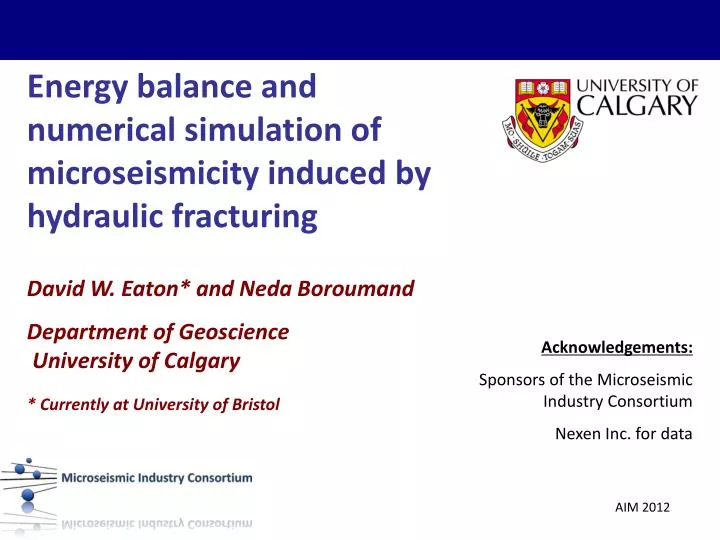
Energy balance and numerical simulation of microseismicity induced by hydraulic fracturing. David W. Eaton* and Neda Boroumand Department of Geoscience University of Calgary * Currently at University of Bristol. Acknowledgements: Sponsors of the Microseismic Industry Consortium

E N D
Energy balance and numerical simulation of microseismicity induced by hydraulic fracturing David W. Eaton* and NedaBoroumand Department of Geoscience University of Calgary * Currently at University of Bristol Acknowledgements: Sponsors of the Microseismic Industry Consortium Nexen Inc. for data
Outline Role of microseismic monitoring in hydraulic fracturing for unconventional oil resource development Energy balance: radiated seismic energy versus frac energy inputs/outputs Numerical simulation of frac-induced microseismicity, based on crack-tip stress and Coulomb Stress field
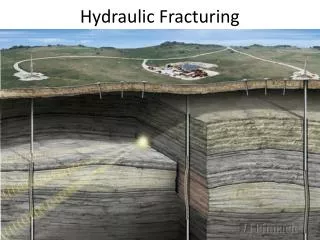
What is hydraulic fracturing? http://www.capp.ca • High-pressure fluids are injected to create tensile fractures, in order to enhance permeability of hydrocarbon-bearing formations • This is followed by injection of proppant (e.g. sand) to hold fractures open • Typically implemented in multiple stages within a horizontal wellbore, often many drilled from a single pad
Hydraulic Fracturing: Role of Microseismic Monitoring • Typically a string of downhole geophones and/or surface array • Real-time monitoring to fine-tune injection program, diagnose issues • Post-frac analysis to assess stimulation program Pettitt, 2010
Input vs Output Energy Fracture Energy (EF) Injection Energy (EI) Pressure Rate Radiated Seismic Energy (ER) Time Strain Energy (ES) http://www.engineeringarchives.com Other (i.e. friction/thermal, hydrostatic, leak-off, etc.)
Injection Energy Pressure (P) Where Q(t) = injection rate, P(t) = surface treatment pressure t1 & t2 are start and end times of treatment Rate (Q) Time
Fracture Energy where <Pd> is the average downhole pressure, <AF> is the single-sided surface area and e is the average fracture width (Walter and Brune, JGR, 1993)
Radiated Seismic Energy Kanamori, 1977 where M0 is moment magnitude, and ES is in Joules … but note missing data in G-R plot
Case Study • 10 frac stages • Microseismicevent locations and magnitudes were provided (geometry was measured) • Pumping data provided
b-value correction Energy per event • b = 1.57, small magnitude events contribute more to total seismic energy • If b < 1.5 then more total energy in larger bins • If b > 1.5, then more energy in successively smaller bins Based on Hanks and Kanamori (1979) Joules Energy per bin Total predicted energy: 4.63e+6J Total observed energy: 1.81e+5J Ratio = 25.6 Joules
Numerical Simulation of Microseismicity • Single tensile crack, growing at constant volumetric rate • Stress field from analytic expressions for crack-tip stress • Event occurrence probability based on associated Coulomb stress • Event magnitudes follow Gutenberg-Richter distribution • Distance-dependent detection threshold
Analytic Formulas for Crack-tip stress • Change in stress due to a tensile (mode I) crack in a linear elastic solid Lawn and Wilshaw, 1975
Crack-tip stress field • Simple model of a tensile crack • Note that stress at the crack tip is greater than background tensile stress
Coulomb Stress Field A measure of the state of stress on a planar surface. • is the change in shear stress • μ the coefficient of friction • n is the normal stress • P is the pore fluid pressure
Coulomb Stress and Aftershocks • Coulomb stress changes calculated for the 23 April 1992 ML=6.1 Joshua Tree Earthquake. • Aftershocks occur preferentially in areas of increased Coulomb stress King et al., 1994
Stochastic Model • 20% probability of failure for CFS >= 80 MPa • Magnitude distribution satisfies Gutenberg-Richter relation with b = 1.5 • Dynamic simulation created by assuming an expanding crack with c ~ t1/2
Detection Threshold Eaton et al., 2011
Conclusions • In this case study, radiated seismic energy - even after correction for catalog incompleteness - represents only a few ppm of the injection energy • An idealized geodynamical simulation framework has been developed that matches some characteristics of field observations, including diffusion-like event migration and presumed receiver-side observational bias