Download
1 / 77
830 likes | 1.13k Views
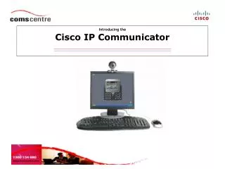
Teldat VisorALARM Plus2U Honeywell IP Communicator Tech Support Training. Nick Martello Martello Consulting Chesterfield, VA. 100% Supervision. Part I: Introduction and Overview. Model Review Part Numbers Ancillary parts Theory of Operation. IP Communicator Review (Obsolete Models).

E N D
Teldat VisorALARMPlus2UHoneywell IP CommunicatorTech Support Training Nick Martello Martello Consulting Chesterfield, VA 100% Supervision
Part I: Introduction and Overview • Model Review • Part Numbers • Ancillary parts • Theory of Operation
Additional Part numbers NOTE: For purposes of this presentation, the Teldat mIP IP UL listed communicator models used in connection to Honeywell Life System fire panels are known as models IPDACT-2 and IPDACT-2UD respectively.
System Overview 90 second supervision
Theory of Operation • The IP Communicators replace the telephone line with an Ethernet connection. • No changes are made to the panel dialer setup. • The IP card simulates a standard PSTN analog line to the panel. • During an event, the IP card senses off-hook status, counts the digits of the dialed phone number then begins collecting Contact ID data. • The IP card “frames” the Contact ID data using UDP packets with 512 bit AES encryption and forwards it to the receiver. • The Receiver decrypts and un-packetizes the data and presents ASCII data to automation software in a preprogrammed format. • The automation software or the receiver can provide the kiss-off signal to the panel.
Theory of Operation-UD • The release of the 2UD models and firmware release 6.0 provides a modem feature to the IP communicator. • This feature uses TCP/IP vs UDP to provide upload/download services to the panel from anywhere in the Internet. • The card contains a V.32 bismodem capable of up to 14,4KB speeds-however most Honeywell Life System fire panels will only operate at a max of 2400 baud. • A special virtual port program is used on the programming PC called UDPORT.exe. This program redirects modem signals from the programming software from the standard ports to a virtual Ethernet port. • The software allows entry of the receiver’s IP address and TCP port to use along with username and password.
Theory of Operation UD-continued • With standard remote programming via PSTN, the user enters a panel phone number to call. • This same number is also used as a database entry in the subscriber field of the target IPDACT db record in the receiver. • Since the VisorALARM “knows” how to poll the remote card, this subscriber field is used as a database lookup for which panel to call. • The on-board modem on the IP card converts the digital encapsulated modem signals back to analog phone signals at the remote site. • The panel then sees a “ring” and answers the call.
Standard Alarm Event Transmission Operation Automation Software (1) Alarm Panel mIP-2/ IPDACT-2UD VisorALARM Dialer capture Serial line Internet Line picked up Calling Contact-ID Alarm IP Alarm Alarm in well-known format Alarm ACK Alarm Kissoff Alarm Kissoff The alarm is never lost on the way: The Alarm is ACK’d only if the Automation Software has kissed it off Call Disconnect (1) Other Automation SW types: IBS, MICROKEY, MASterMind, BOLD, DICE
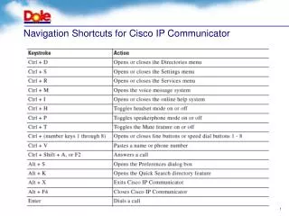
Part II: Network Concepts • IP Address Formats • Subnetting • Determining a Network Address • IP Calc • Private Networks and Subnets • The importance of defining the receiver as “classless” • Ping • Traceroute • http://Network Tools.com • IP Transmission Concepts • NAPT (Network Address Port Translation) • Teldat Security Concepts (ARLY)
IP address format: octet.octet.octet.octet The IP address and mask defines the IP network address and host network address Example: In order for a device to reach any host in a remote (i.e. different) IP network, a default Gateway is required. It is the default gateway’s responsibility to transfer the IP traffic to the remote network. IP Address Concepts 192.198.1.200 /24 Mask: “/24” = “255.255.255.0” Network Host 14
IP Addresses and Subnets • Sub netting works by applying the concept of extended network addresses to individual computer (and other network device) addresses. • An extended network address includes both a network address and additional bits that represent the subnet number... (see below) • Together, these two data elements support a two-level addressing scheme recognized by standard implementations of IP. The network address and subnet number, when combined with the host address, therefore support a three-level scheme
Understanding IP Addresses Private Intranet For every additional bit set to '1' in the mask, another bit becomes available in the subnet number to index additional subnets. A two-bit subnet number can support up to four subnets, a three-bit number supports up to eight subnets, and so on.
Private Networks and Subnets • The governing bodies that administer Internet Protocol have reserved certain networks for internal uses. • In general, intranets utilizing these networks gain more control over managing their IP configuration and Internet access. • This sub-netting permits organizations to prohibit access to machines from certain other machines. • The default subnet masks associated with theseprivate networks are listed below.
Classless Routing • Classless Inter-Domain Routing (CIDR) is a mechanism introduced to slow the growth of routing tables on routers across the internet, and to help prevent waste of IP addresses by allocating a subset (as opposed to whole chunks) of a Class A, B ,or C network to ISP's and organizations. • It allows for address specified in CIDR notation, address aggregation and easier delegation of address blocks. • It is important to include the term classless in the receiver’s config file just below the router entry. • Failure to do so may cause routing problems and “lost” mIPS. • See “Fine Tuning” the configuration later in this presentation.
Basic Useful IP Tests-PING • The ping utility checks whether a host is alive and reachable or not. This is done by sending an ICMP Echo Request packet to the host, and waiting for an ICMP Echo Reply from the host. (See example below)
Basic Useful IP Tests-Traceroute • Traceroute is a program that can show the route over the network between two systems, listing all the intermediate routers a connection must pass through to get to its destination. • It can help determine why connections to a given server might be poor, and can often help determine where exactly the problem is. • It can also show how systems are connected to each other, letting you see how an ISP connects to the Internet as well as how the target system is connected. • Easy to use Traceroute tools are available even for Vista. • Go to http://network-tools.com/
IP transmission basic concepts Peer-to-peer Host A Host B TCP/UDP TCP/UDP IP IP Link Link Def GW for host B Def GW for host A IP Network 22
Teldat IP Basics -IPDACT Security • Highest security level in the industry: • All IP traffic exchanged is encrypted with a 512-bit AES algorithm (Grade AA for UL1610). • The configuration access is password protected. • IPDACT installer & configuration passwords can be centrally managed. • Any IPDACT parameter can be managed from the central station via individual IP address or group config pattern. • Anti-device substitution protection based on non-writable IPDACT specific information. • Anti-replay protection to avoid man-in-the-middle attacks • ‘sequential marked’ frames.
Teldat IP Basics -Supervision • Firewall compatibility: • All communication begins at the IPDACT side so it becomes a trusted host behind the customer’s firewall. • The IPDACT to VisorALARM communication only requires one UDP port. • Low UDP bandwidth vs TCP/IP: • Contact frame (once, when IPDACT boots up) 72 bytes • Polling frames 24 bytes • Alarm frames 56 bytes • IP comm. supervision. • PSTN supervision. • Supported by both IPDACT and Fire panels. • Alarm panel supervises in Fire scenarios.
Teldat IP Basics- Communication Highlights: ARLY Internet ARLY protocol • ARLY is the protocol used between the mIP/IPDACT and the VisorALARM • Three services run on ARLY Alarm Transmission Account Supervision Upload / Download • Savesbandwidth in theARC’s IP service • ARLY runsover UDP/IP Lessbandwidthconsumingthan TCP/IP solutions • Reliablecommunications: • ARLY addsrobustnessto UDP withpacketsequencing and retransmissions • BackupVisorALARMservesmIP/IPDACT’siftheMainVisorALARMisdown • Firewall friendly • The Security Servicejustrequiresone open port in the ARC access Firewalls • No open portsrequired in thecustomer’s Firewall
The IP packet format & NAPT IP SOURCE ADDRESS IP DESTINATION ADDRESS UDP SOURCE PORT UDP DESTINATION PORT IP packet ARLY PROTOCOL PAYLOAD Encapsulated UDP packet NAPT The IP packet sent by the IPDACT has private source IP address and source UDP port When the IP packet traverses the customer access router, on its way to the Internet, the source IP address and UDP port is translated to public ones. When the IP packet traverses the customer access router, on its way to the IPDACT (opposite direction), inverse translation takes place: destination public IP address & port is translated to the private ones. 26
Scenario 1: IPDACT and VisorALARM behind a NAPT router • In a typical scenario, the IPDACT and VisorALARM default gateways are connected to the Internet. • UDP frames transmitted to the Internet through these gateways are hence modified according to NAPT (Network Address Port Translation). • The following diagram illustrates a network diagram for this scenario as well as the UDP frame header parameters in each network segment (subscriber network, the Internet and the ARC network):
IPDACT and VisorALARM behind a NAPT router • As shown in the drawing, both routers need to do NAPT so the transmitted UDP frame travels along the Internet with the system public IP addresses (213.4.21.187 and 80.26.96.183 in the Figure). For the correct system operation, the subscriber’s network firewall should allow: • UDP traffic sent from the IPDACT (IP address: 192.168.1.2 in the example) to the ARC public IP address (80.26.96.183 in the example).
IPDACT and VisorALARM behind a NAPT router • On transmission, the subscriber’s default gateway sets a NAPT conversion entry in its cache memory, so the received UDP traffic from the Internet can be forwarded back to the IPDACT. • UDP traffic received from the ARC (80.26.96.183). The subscriber’s default gateway will forward this traffic to the IPDACT (192.168.1.2) according to its cached NAPT entry.
IPDACT and VisorALARM behind a NAPT router • In analogy, the ARC network firewall should allow: • UDP traffic received from the Internet to its serving port (port 80 in the example). Traffic to this port should be triggered to the VisorALARM (IP address: 172.24.4.1, serving port 80). • UDP traffic sent from the VisorALARM to the Internet
Teldat IP Basics -IPDACT Security • Highest security level in the industry: • All IP traffic exchanged is encrypted with a 512-bit AES algorithm (Grade AA for UL1610). • The configuration access is password protected. • IPDACT installer & configuration passwords can be centrally managed. • Any IPDACT parameter can be managed from the central station via individual IP address or group config pattern. • Anti-device substitution protection based on non-writable IPDACT specific information. • Anti-replay protection to avoid man-in-the-middle attacks • ‘sequential marked’ frames.
Teldat IP Basics -Supervision • Firewall compatibility: • All communication begins at the IPDACT side so it becomes a trusted host behind the customer’s firewall. • The IPDACT to VisorALARM communication only requires one UDP port. • Low UDP bandwidth vs TCP/IP: • Contact frame (once, when IPDACT boots up) 72 bytes • Polling frames 24 bytes • Alarm frames 56 bytes • IP comm. supervision. • PSTN supervision. • Supported by both IPDACT and Fire panels. • Alarm panel supervises in Fire scenarios.
Part III: Servicing Receiver Customers • Recommended Tools • IPDACT programming • Reducing Customer Frustration • Initial Bench Receiver Settings
Recommended Tools For Tech Support Site • TeraTerm-Pro Shareware but better terminal program than HyperTerminal which does not come with Vista or Windows 7. • Used for programming: • IPDACT via Telnet or serial connection • VisorALARM Plus via Telnet or serial connection • IPDACT Windows Programming Tool • Used for programming IPDACT in field • Actually a Windows application front end for Telnet • VisorALARM Manager-A Windows application for Telnet • FTP client (Available on Vista/Windows 7) • Used for upgrading receivers • RFU: Rabbit Field Utility • Used for upgrading IPDACT firmware from a PC • Ping-Used to determine access to an IP address
Basic IP-Card Programming Requirements • IPDACT default access password (factory default is 24680). This is NOT the install password • “Installator” password, required to execute the register command. (Called “Installator” password to separate from default access password) • If STATIC IP is to be used such as in an enterprise or corporation: Obtain IP address, subnet mask and Internet gateway for IPDACT from enterprise IT manager. • Default IP is 192.168.0 100 with subnet of 255.255.255.0 (Card ships defaulted to DHCP) • IPDACT account number or client number • IP addresses of the Primary and Secondary VisorALARM central station receivers • UDP Port number to use
IPDACT Windows Installer Tool Automatically finds IPDACT
IPDACT Windows Installer Tool Automatically finds IPDACT
Eliminate Setup Frustration • Central Station Operators should contact tech support before opening the box! • Obtain or download programming tools including TeraTermPro. • Downloads: • Download the latest version of VisorALARM Manager. • After determining firmware version decide if receiver needs firmware upgrade before continuing. • This can be accomplished via the monitor program inside VM or via simple serial terminal connection and turning it on.
Eliminate Setup Frustration for New Customers • If possible, set up receiver on bench before mounting in rack • Connect via serial cable to set basic parameters such as: • IP address • Gateway • Port numbers • After preliminary settings, system can be rack mounted and accessed via Telnet from the programmer’s desk. • This process will eliminate a lot of frustration!
Tera-Term Pro setup • Using the supplied DB9M to DB9F serial cable connect to receiver first via serial port. • Set Tera-Term window to 40 lines –this allows more of the config to be seen without scrolling
A new session of Tera-Term is defaulted to COM 1 • Connect first via the DB9 serial port on the back of the receiver –setup is standard 9600, 8, n, 1
Initial Settings • Upon connection, hit enter to start the session • Enter manager for User: • Enter 24680 for password and the following should appear:
Changing IP address of the receiver • Determine existing IP address (should be 192.168.0.200) • At the * prompt, enter p 4 (p-space-4) and the following screen should appear:
Changing IP address of the receiver • At the Config> prompt, type “show all” and the following screen will scroll to the bottom of the config file: (exit) Note the IP address below:
Changing IP address of the receiver • At the Config> prompt, Enter the following commands, protocol ip • The receiver will respond with the following prompt: • IP config>
Changing IP address of the receiver • Type the following text to change the IP address • IP Config>address Ethernet 0/0 XXX.XXX.XXX.XXX (spc) 255.255.0.0 or what ever the mask to be used. • Keep in mind the mask works in conjunction with the network numbers to limit the number of machines that can exist on the network or to divide subnets to prevent machines from accessing other machines. • Once this is complete, the user can connect with VisorALARM Manager. This will make the setup go much faster and cause less frustration. • To exit from IPCONFIG, type exit to return to Config> • Save the configuration by type sa(save) • Respond to “save configuration? –type y (yes) • Then type <CtrL>P to exit to the * prompt • Type re for restart to start the receiver with the changed IP address.
Part IV VisorALARM Manager • Logging In • Set Global Parameters • The Monitor Program • Determining Firmware Rev and Bios Rev • Determining mIP on-line/off line-status • Adjusting User-Defined Contact ID Codes • Viewing Registered Accounts • Setting up Configuration Patterns
VisorALARM Manager Initial Setup • VisorALARM Manager is actually a Visual Basic front end to Telnet. • If the actual IP address is not entered correctly, the session will not start. • Enter does not work-click on OK with the mouse.