Download
1 / 53
540 likes | 739 Views
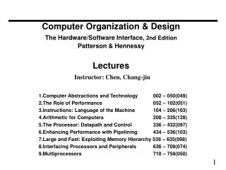
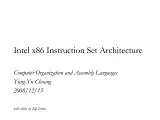
55:035 Computer Architecture and Organization. Lecture 10. Outline. Pipelining Basics Throughput Execution Time Pipeline Registers Program Execution Hazards Structural Data Control. ILP: Instruction Level Parallelism.

E N D
55:035Computer Architecture and Organization Lecture 10
Outline • Pipelining • Basics • Throughput • Execution Time • Pipeline Registers • Program Execution • Hazards • Structural • Data • Control 55:035 Computer Architecture and Organization
ILP: Instruction Level Parallelism • Single-cycle and multi-cycle datapaths execute one instruction at a time. • How can we get better performance? • Answer: Execute multiple instruction at a time: • Pipelining – Enhance a multi-cycle datapath to fetch one instruction every cycle. • Parallelism – Fetch multiple instructions every cycle. 55:035 Computer Architecture and Organization
Automobile Team Assembly 1 hour 1 hour 1 hour 1 hour • 1 car assembled every four hours • 6 cars per day • 180 cars per month • 2,040 cars per year 55:035 Computer Architecture and Organization
Automobile Assembly Line Task 2 1 hour Task 3 1 hour Task 4 1 hour Task 1 1 hour Mecahnical Electrical Painting Testing First car assembled in 4 hours (pipeline latency) thereafter 1 car per hour 21 cars on first day, thereafter 24 cars per day 717 cars per month 8,637 cars per year 55:035 Computer Architecture and Organization
Throughput: Team Assembly Red car started Red car completed Mechanical Electrical Painting Testing Mechanical Electrical Painting Testing Blue car started Blue car completed Time Time of assembling one car = n hours where n is the number of nearly equal subtasks, each requiring 1 unit of time Throughput = 1/n cars per unit time 55:035 Computer Architecture and Organization
Throughput: Assembly Line Mechanical Electrical Painting Testing Car 1 Car 2 Car 3 Car 4 . . Mechanical Electrical Painting Testing Mechanical Electrical Painting Testing Mechanical Electrical Painting Testing Car 1 complete Car 2 complete time Time to complete first car = n time units (latency) Cars completed in time T = T – n + 1 Throughput = 1- (n - 1)/ T car per unit time Throughput (assembly line) 1 – (n - 1)/ Tn (n – 1) ─────────────────── = ──────── = n – ───── → n Throughput (team assembly) 1/nT as T→∞ 55:035 Computer Architecture and Organization
Some Features of Assembly Line Electrical parts delivered (JIT) Task 2 1 hour Task 3 1 hour Task 4 1 hour Task 1 1 hour Mechanical Electrical Painting Testing 3 cars in the assembly line are suspects, to be removed (flush pipeline) Defect found Stall assembly line to fix the cause of defect 55:035 Computer Architecture and Organization
Pipelining in a Computer • Divide datapath into nearly equal tasks, to be performed serially and requiring non-overlapping resources. • Insert registers at task boundaries in the datapath; registers pass the output data from one task as input data to the next task. • Synchronize tasks with a clock having a cycle time that just exceeds the time required by the longest task. • Break each instruction down into a fixed number of tasks so that instructions can be executed in a staggered fashion. 55:035 Computer Architecture and Organization
Single-Cycle Datapath No operation on data; idle time equalizes instruction length to a fixed clock period. 55:035 Computer Architecture and Organization
Execution Time: Single-Cycle 0 2 4 6 8 10 12 14 16 . . Time (ns) lw $1, 100($0) lw $2, 200($0) lw $3, 300($0) IF ID EX MEM WB IF ID EX MEM WB IF ID EX MEM WB Clock cycle time = 8 ns Total time for executing three lw instructions = 24 ns 55:035 Computer Architecture and Organization
Pipelined Datapath No operation on data; idle time inserted to equalize instruction lengths. 55:035 Computer Architecture and Organization
Execution Time: Pipeline 0 2 4 6 8 10 12 14 16 . . Time (ns) lw $1, 100($0) lw $2, 200($0) lw $3, 300($0) IF ID EX MEM RW IF ID EX MEM RW IF ID EX MEM RW Clock cycle time = 2 ns, four times faster than single-cycle clock Total time for executing three lw instructions = 14 ns Single-cycle time 24 Performance ratio = ──────────── = ── = 1.7 Pipeline time 14 55:035 Computer Architecture and Organization
Pipeline Performance Clock cycle time = 2 ns 1,003 lw instructions: Total time for executing 1,003 lw instructions = 2,014 ns Single-cycle time 8,024 Performance ratio = ──────────── = ──── = 3.98 Pipeline time 2,014 10,003 lw instructions: Performance ratio = 80,024 / 20,014 = 3.998 → Clock cycle ratio (4) Pipeline performance approaches clock-cycle ratio for long programs. 55:035 Computer Architecture and Organization
Single-Cycle Datapath WB: writeback ID: Instr. decode, reg. file read EX: Execute, address calc. MEM: mem. access IF: Instr. fetch 4 Add 1 mux 0 ALU Branch opcode MemtoReg CONTROL 26-31 RegWrite ALUSrc 21-25 zero MemWrite MemRead ALU Instr. mem. PC Reg. File Data mem. 1 mux 0 16-20 0 mux 1 1 mux 0 11-15 RegDst ALUOp ALU Cont. Sign ext. Shift left 2 0-15 0-5 55:035 Computer Architecture and Organization
Pipelining of RISC Instructions Fetch Instruction Examine Opcode Fetch Operands Perform Operation Store Result IF ID EX MEM WB Instruction Decode Execute Memory Write Fetch instruction and Operation Back Fetch operands to Reg file Although an instruction takes five clock cycles, one instruction is completed every cycle. 55:035 Computer Architecture and Organization
Pipeline Registers IF/ID ID/EX EX/MEM 4 1 mux 0 Add ALU Branch opcode MemtoReg CONTROL 26-31 MEM/WB RegWrite ALUSrc 21-25 zero MemWrite MemRead ALU Instr. mem. PC Reg. File Data mem. 16-20 1 mux 0 0 mux 1 1 mux 0 11-15 This requires a CONTROL not too different from single-cycle RegDst ALUOp ALU Cont. Sign ext. Shift left 2 0-15 0-5 55:035 Computer Architecture and Organization
Pipeline Register Functions • Four pipeline registers are added: 55:035 Computer Architecture and Organization
Pipelined Datapath IF/ID ID/EX EX/MEM MEM/WB 4 1 mux 0 Add ALU opcode Shift left 2 26-31 zero 21-25 Instr mem ALU Data mem 16-20 Reg. File PC 1 mux 0 0 mux 1 Sgn ext 11-15 for R-type 16-20 for I-type lw 0-15 55:035 Computer Architecture and Organization
DM IM ID, REG. FILE READ ALU REG. FILE WRITE MEM/WB IF/ID ID/EX EX/MEM Five-Cycle Pipeline CC1 CC2 CC3 CC4 CC5 55:035 Computer Architecture and Organization
Add Instruction • add $t0, $s1, $s2 • Machine instruction word • 000000 10001 10010 01000 00000 100000 • opcode $s1 $s2 $t0 function CC1 CC2 CC3 CC4 CC5 DM IM ID, REG. FILE READ ALU REG. FILE WRITE MEM/WB IF/ID ID/EX EX/MEM IF ID EX MEM WB read $s1 add write $t0 read $s2 $s1+$s2 55:035 Computer Architecture and Organization
Pipelined Datapath Executing add IF/ID ID/EX EX/MEM MEM/WB 4 Add 1 mux 0 ALU opcode Shift left 2 26-31 s1 zero $s1 21-25 ALU addr Data mem data Instr mem 16-20 Reg. File PC $s2 s2 1 mux 0 0 mux 1 Sign ext. 11-15 for R-type 16-20 for I-type lw t0 0-15 55:035 Computer Architecture and Organization
DM IM ID, REG. FILE READ ALU REG. FILE WRITE MEM/WB IF/ID ID/EX EX/MEM Load Instruction • lw $t0, 1200 ($t1) • 100011 01001 01000 0001 0010 0000 0000 • opcode $t1 $t0 1200 CC1 CC2 CC3 CC4 CC5 IF ID EX MEM WB read $t1 add read write $t0 sign ext $t1+1200 M[addr] 1200 55:035 Computer Architecture and Organization
Pipelined Datapath Executing lw IF/ID ID/EX EX/MEM MEM/WB 4 1 mux 0 Add ALU opcode Shift left 2 26-31 t1 zero $t1 21-25 ALU Instr mem addr Data mem data 16-20 Reg. File PC 1 mux 0 0 mux 1 Sign ext. 11-15 for R-type 16-20 for I-type lw t0 0-15 1200 55:035 Computer Architecture and Organization
DM IM ID, REG. FILE READ ALU REG. FILE WRITE MEM/WB IF/ID ID/EX EX/MEM Store Instruction • sw $t0, 1200 ($t1) • 101011 01001 01000 0001 0010 0000 0000 • opcode $t1 $t0 1200 CC1 CC2 CC3 CC4 CC5 IF ID EX MEM WB read $t1 add write sign ext $t1+1200 M[addr] 1200 (addr) ← $t0 55:035 Computer Architecture and Organization
Pipelined Datapath Executing sw IF/ID ID/EX EX/MEM MEM/WB 4 1 mux 0 Add ALU opcode Shift left 2 26-31 t1 zero $t1 21-25 ALU addr Data mem data Instr mem 16-20 Reg. File PC $t0 t0 1 mux 0 0 mux 1 Sign ext. 11-15 for R-type 16-20 for I-type lw 0-15 1200 55:035 Computer Architecture and Organization
Executing a Program Consider a five-instruction segment: lw $10, 20($1) sub $11, $2, $3 add $12, $3, $4 lw $13, 24($1) add $14, $5, $6 55:035 Computer Architecture and Organization
DM DM DM DM DM ID, REG. FILE READ IM ALU REG. FILE WRITE ID, REG. FILE READ ID, REG. FILE READ ALU ALU REG. FILE WRITE REG. FILE WRITE IM IM ID, REG. FILE READ ID, REG. FILE READ ALU ALU IM IM REG. FILE WRITE REG. FILE WRITE MEM/WB MEM/WB MEM/WB MEM/WB MEM/WB IF/ID EX/MEM ID/EX EX/MEM EX/MEM ID/EX ID/EX IF/ID IF/ID EX/MEM EX/MEM IF/ID IF/ID ID/EX ID/EX Program Execution time CC1 CC2 CC3 CC4 CC5 lw $10, 20($1) sub $11, $2, $3 Program instructions add $12, $3, $4 lw $13, 24($1) add $14, $5, $6 55:035 Computer Architecture and Organization
CC5 MEM: sub $11, $2, $3 WB: lw $10, 20($1) IF: add $14, $5, $6 ID: lw $13, 24($1) EX: add $12, $3, $4 IF/ID ID/EX EX/MEM MEM/WB 4 1 mux 0 Add ALU opcode Shift left 2 26-31 zero 21-25 Instr mem ALU 16-20 Data mem. Reg. File PC 1 mux 0 0 mux 1 Sign ext. 11-15 for R-type 16-20 for I-type lw 0-15 55:035 Computer Architecture and Organization
Advantages of Pipeline • After the fifth cycle (CC5), one instruction is completed each cycle; CPI ≈ 1, neglecting the initial pipeline latency of 5 cycles. • Pipeline latency is defined as the number of stages in the pipeline, or • The number of clock cycles after which the first instruction is completed. • The clock cycle time is about four times shorter than that of single-cycle datapath and about the same as that of multicycle datapath. • For multicycle datapath, CPI = 3. …. • So, pipelined execution is faster, but . . . 55:035 Computer Architecture and Organization
Pipeline Hazards • Definition: Hazard in a pipeline is a situation in which the next instruction cannot complete execution one clock cycle after completion of the present instruction. • Three types of hazards: • Structural hazard (resource conflict) • Data hazard • Control hazard 55:035 Computer Architecture and Organization
Structural Hazard • Two instructions cannot execute due to a resource conflict. • Example: Consider a computer with a common data and instruction memory. The fourth cycle of a lw instruction requires memory access (memory read) and at the same time the first cycle of the fourth instruction requires instruction fetch (memory read). This will cause a memory resource conflict. 55:035 Computer Architecture and Organization
Example of Structural Hazard CC1 CC2 CC3 CC4 CC5 time IM/DM ALU REG. FILE WRITE ID, REG. FILE READ IM/DM lw $10, 20($1) MEM/WB ID/EX EX/MEM IF/ID IM/DM ID, REG. FILE READ ALU REG. FILE WRITE IM/DM MEM/WB EX/MEM IF/ID ID/EX sub $11, $2, $3 Common data and instr. Mem. IM/DM ID, REG. FILE READ ALU IM/DM REG. FILE WRITE MEM/WB EX/MEM IF/ID ID/EX add $12, $3, $4 Program instructions IM/DM ID, REG. FILE READ ALU IM/DM REG. FILE WRITE MEM/WB IF/ID ID/EX EX/MEM lw $13, 24($1) Needed by two instructions 55:035 Computer Architecture and Organization
Possible Remedies for Structural Hazards • Provide duplicate hardware resources in datapath. • Control unit or compiler can insert delays (no-op cycles) between instructions. This is known as pipeline stall or bubble. 55:035 Computer Architecture and Organization
Stall (Bubble) for Structural Hazard time CC1 CC2 CC3 CC4 CC5 IM/DM ID, REG. FILE READ IM/DM ALU REG. FILE WRITE lw $10, 20($1) MEM/WB IF/ID ID/EX EX/MEM IM/DM ALU IM/DM ID, REG. FILE READ REG. FILE WRITE sub $11, $2, $3 MEM/WB EX/MEM ID/EX IF/ID IM/DM IM/DM ID, REG. FILE READ ALU REG. FILE WRITE add $12, $3, $4 MEM/WB IF/ID ID/EX EX/MEM Program instructions Stall (bubble) IM/DM ID, REG. FILE READ ALU IM/DM REG. FILE WRITE lw $13, 24($1) MEM/WB EX/MEM IF/ID ID/EX 55:035 Computer Architecture and Organization
Data Hazard • Data hazard means that an instruction cannot be completed because the needed data, being generated by another instruction in the pipeline, is not available. • Example: consider two instructions: • add $s0, $t0, $t1 • sub $t2, $s0, $t3 # needs $s0 55:035 Computer Architecture and Organization
Example of Data Hazard time CC1 CC2 CC3 CC4 CC5 Write s0 in CC5 DM ID, REG. FILE READ ALU REG. FILE WRITE IM add $s0, $t0, $t1 ID/EX EX/MEM MEM/WB IF/ID DM REG. FILE WRITE ID, REG. FILE READ IM ALU sub $t2, $s0, $t3 MEM/WB IF/ID ID/EX EX/MEM Read s0 and t3 in CC3 Program instructions We need to read s0 from reg file in cycle 3 But s0 will not be written in reg file until cycle 5 However, s0 will only be used in cycle 4 And it is available at the end of cycle 3 55:035 Computer Architecture and Organization
Forwarding or Bypassing • Output of a resource used by an instruction is forwarded to the input of some resource being used by another instruction. • Forwarding can eliminate some, but not all, data hazards. 55:035 Computer Architecture and Organization
Forwarding for Data Hazard CC1 CC2 CC3 CC4 CC5 time Write s0 in CC5 DM ID, REG. FILE READ REG. FILE WRITE ALU IM add $s0, $t0, $t1 MEM/WB ID/EX EX/MEM IF/ID Forwarding DM ID, REG. FILE READ ALU IM REG. FILE WRITE sub $t2, $s0, $t3 IF/ID ID/EX EX/MEM MEM/WB Read s0 and t3 in CC3 Program instructions 55:035 Computer Architecture and Organization
Forwarding Unit Hardware ID/EX EX/MEM MEM/WB FORW. MUX ALU Data Mem. Data to reg. file MUX FORW. MUX Destination registers Source reg. IDs from opcode Forwarding Unit 55:035 Computer Architecture and Organization
Forwarding Alone May Not Work time CC1 CC2 CC3 CC4 CC5 Write s0 in CC5 DM ID, REG. FILE READ ALU REG. FILE WRITE IM lw $s0, 20($s1) MEM/WB EX/MEM ID/EX IF/ID DM ID, REG. FILE READ ALU REG. FILE WRITE IM sub $t2, $s0, $t3 MEM/WB EX/MEM IF/ID ID/EX Read s0 and t3 in CC3 Program instructions data needed by sub (data hazard) data available from memory only at the end of cycle 4 55:035 Computer Architecture and Organization
Use Bubble and Forwarding time CC1 CC2 CC3 CC4 CC5 Write s0 in CC5 DM ALU REG. FILE WRITE ID, REG. FILE READ IM lw $s0, 20($s1) ID/EX MEM/WB EX/MEM IF/ID stall (bubble) Forwarding DM ALU IM REG. FILE WRITE ID, REG. FILE READ IF/ID ID/EX EX/MEM MEM/WB sub $t2, $s0, $t3 Program instructions 55:035 Computer Architecture and Organization
Hazard Detection Unit Hardware Disable write Hazard Detection Unit ID/EX EX/MEM MEM/WB Control FORW. MUX ALU NOP MUX Data Mem. 0 PC FORW. MUX Instruction to reg. file IF/ID Control signals Forwarding Unit Source reg. IDs from opcode 55:035 Computer Architecture and Organization
Resolving Hazards • Hazards are resolved by Hazard detection and forwarding units. • Compiler’s understanding of how these units work can improve performance. 55:035 Computer Architecture and Organization
Avoiding Stall by Code Reorder C code: A = B + E; C = B + F; MIPS code: lw $t1, 0($t0) . $t1 written lw $t2, 4($t0) . . $t2 written add $t3, $t1, $t2 . . . $t1, $t2 needed sw $t3, 12($t0) . . . . lw $t4, 8($t0) . . . . . $t4 written add $t5, $t1, $t4 . . . . . $t4 needed sw $t5, 16,($t0) . . . . . . . . . . . . . . . 55:035 Computer Architecture and Organization
Reordered Code C code: A = B + E; C = B + F; MIPS code: lw $t1, 0($t0) lw $t2, 4($t0) lw $t4, 8($t0) add $t3, $t1, $t2no hazard sw $t3, 12($t0) add $t5, $t1, $t4no hazard sw $t5, 16,($t0) 55:035 Computer Architecture and Organization
Control Hazard • Instruction to be fetched is not known! • Example: Instruction being executed is branch-type, which will determine the next instruction: • add $4, $5, $6 • beq $1, $2, 40 • next instruction • . . . • 40 and $7, $8, $9 55:035 Computer Architecture and Organization
DM DM DM ID, REG. FILE READ IM ALU REG. FILE WRITE ID, REG. FILE READ ALU REG. FILE WRITE IM ID, REG. FILE READ ALU IM REG. FILE WRITE MEM/WB MEM/WB MEM/WB IF/ID EX/MEM ID/EX EX/MEM ID/EX EX/MEM IF/ID IF/ID ID/EX Stall on Branch time CC1 CC2 CC3 CC4 CC5 add $4, $5, $6 beq $1, $2, 40 Program instructions Stall (bubble) next instruction or and $7, $8, $9
Why Only One Stall? • Extra hardware in ID phase: • Additional ALU to compute branch address • Comparator to generate zero signal • Hazard detection unit writes the branch address in PC 55:035 Computer Architecture and Organization
Ways to Handle Branch • Stall or bubble • Branch prediction: • Heuristics • Next instruction • Prediction based on statistics (dynamic) • Hardware decision (dynamic) • Prediction error: pipeline flush • Delayed branch 55:035 Computer Architecture and Organization