Download
1 / 31
380 likes | 694 Views
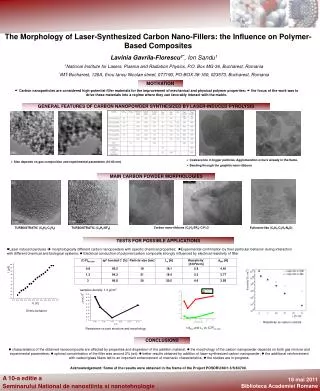
On the effects of thickness on delamination of polymer composites. J. Botsis, B. D. Manshadi, E. Farmand-Ashtiani. École Polytechnique Fédérale de Lausanne (EPFL), Lausanne, Switzerland. COMPUTATIONAL AND EXPERIMENTAL MECHANICS OF ADVANCED MATERIALS (CEMAM) July 1 - 3, 2013; KAUST. Outline.

E N D
On the effects of thickness on delamination of polymer composites J. Botsis,B. D. Manshadi,E. Farmand-Ashtiani École Polytechnique Fédérale de Lausanne (EPFL), Lausanne, Switzerland COMPUTATIONAL AND EXPERIMENTAL MECHANICS OF ADVANCED MATERIALS (CEMAM) July 1 - 3, 2013; KAUST
Outline • Introduction: Delamination & bridging in uniaxially reinforced composites • Motivation - objective • Methods : • Materials and specimens • Embedded FBG for internal strain measurements • Numerical /Analytical approach • Results : • Experimental • Analytical/numerical • Conclusions
Delamination & bridging Unidirectional composites in DCB testing AS4 / PPS Carbon / Epoxy Large Scale Bridging Glass / polyester Specimen size is important …………….........
ERR vs thickness Studies on thicknesseffects on delaminationand bridging Davis et all on IM6/PEEK Hojo & Aoki on AS4/PEEK and T800/Epoxy Sorensen & Jacobsen on Signafil CE 1007 Spearing & Evans on ceramic composites Tamuz et all on Carbon/epoxy ………..
ERR vs thickness Sorensen & Jacobsen on Signafil CE 1007 Tamuz et all on Carbon/epoxy
Delamination & bridging ERR vs thickness: Strong R-curve effects Carbon - epoxy Glass –polyester Initiation value
d* = d(a) Gb GIC Evaluation of bridging tractions Evaluation of bridging tractions: Direct Method
Evaluation of bridging tractions Evaluation of bridging tractions Problems: • Since the bridging law is the result of the differentiation of ERR and COD, the fit of the experimental data significantly influences the stress distribution, especially near the crack tip. • it is very difficult to locate the end of the bridging zone and the corresponding COD used in the data reduction
Evaluation of bridging tractions When experimental data on COD are available, the COD-bridging traction relation offers an indirect method to measure the tractions. Such methods, necessitate highly accurate measurements of the COD profiles for reliable evaluations of the associated bridging tractions. Experimentally it is very difficult to achieve. COD measured Bridging tractions Weight function
Objective Observation Characterise bridging tractions in polymer matrix composites and the effects of specimen size : use embedded FBG sensors for internal strain measurements during delamination. develop iterative numerical/analytical modelling and optimisation tools to evaluate relevant parameters and tractions. ERR at initiation is well characterized and independent of the specimen thickness. Propagation values rise up to a plateau value (R-curve): - strong influence of thickness. Objective
Methods : Bridging tractions Evaluation of bridging tractions
Methods : FBG – multiplexing Quasi-distributed sensing z For each sensor
A1 sb g -A1/A2 Methods : bridging tractions sb • Distributed strain data are used • Bridging stress distribution is taken as • A1 : maximum bridging stress stress, sbmax • A1/A2 : bridging zone length, g : curvature
Methods : bridging tractions sb Define an error norm describing the difference between the simulated and measured strains mean value Identification is reduced to the optimization problem Find a such that with constraints : Where Adopt: Non-linear least squares minimization Trust region reflective Newtonian algorithm to solve the constrained non-linear least square optimization problem
Methods : materials Specimens DCB specimens were produced with different lengths and different nominal thicknesses h ranging from 3.5 mm to 19.0 mm. A 60 mm long release film with a 20 μm thickness was introduced in the mid-plane of each plate to create the pre-crack. In two selected specimens we embed optical fibers with several strain sensors above the delamination plane. Material GFRP (polyester glass) plates were fabricated by wet hand-lay-up of several layers of unidirectional E-glass fiber fabrics cured at 25°C for 7 days. The number of layers/specimen was proportionally increased with the specimen thickness indicating a maximum of 3% in variation on volume fraction between the specimens.
Methods : specimens Intralaminar crack Interlaminar crack specimen orientation Matrix rich zones
Results : FBG – multiplexing Quasi-distributed sensing
Results: L-D & strains Load – displacement curves Typical strain-time data
Results : FBG – strain data Strain - time data curves Strain - crack length data
Results : ERR vs thickness The response of all specimens is linear elastic. Compliance was measured during testing. The steady state ERR varied from 900 (h=3.5mm) to 2100J/m2 (h = 19mm) Initiation value
Results : bridging tractions sb The identified parameters for the specimens of h = 5.4 and 14.2 mm for h = 5.41 mm are : γ = 0.110, zmax = 52.5 mm, σmax = 2.10 MPa , and dmax = 12 mm for h = 14.2 mm are : γ = 0.048, zmax = 90.4 mm, σmax = 2.15 MPa. and dmax = 12 mm
Results : bridging tractions sb Combining the identified traction distribution and the COD, δ, from FE-model, traction-opening behavior σb(δ) is obtained.
Results : scaling parameter Analysis and experiments confirm the increase in the fiber bridging zone, zmax, with increasing thickness. BUT the identified parameters σmax~2.1 MPa and δmax ~12 mm, do not depend on the beam thickness. Hypothesis (based on results & physical considerations): σmax~2.1 MPa and δmax ~12 mm should be independent of thickness for a given material system.
Results : ERR vs thickness Limiting value of ERR??
Results : CZ modeling Load-displacement predictions h=5.4; 14.2 mm h=3.5; 10.1; 19.0 mm
Conclusions 1. Specimen thickness has an important effect on the steady value of the ERR. 2. The proposed method of analysis indicates that for a given composite: MAX bridging stress and MAX COD at the end of the bridging zone are material constants. 3. The parameter responsible for the thickness effect is the rate of change of the traction distribution. (a linear bridging relation cannot account for scale effects).