Download
1 / 44
440 likes | 592 Views
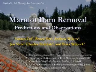
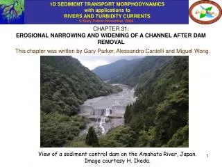
CHAPTER 31: EROSIONAL NARROWING AND WIDENING OF A CHANNEL AFTER DAM REMOVAL. This chapter was written by Gary Parker, Alessandro Cantelli and Miguel Wong. View of a sediment control dam on the Amahata River, Japan. Image courtesy H. Ikeda. CONSIDER THE CASE OF THE SUDDEN REMOVAL,

E N D
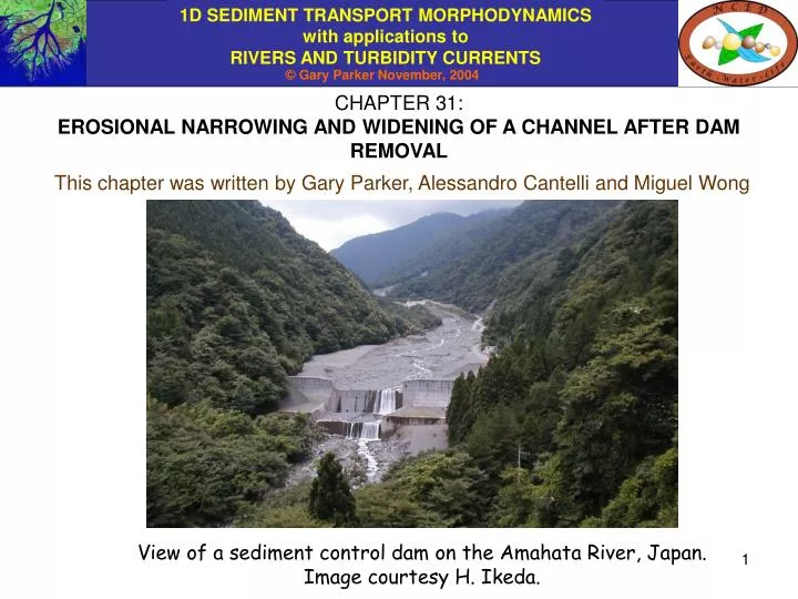
CHAPTER 31: EROSIONAL NARROWING AND WIDENING OF A CHANNEL AFTER DAM REMOVAL This chapter was written by Gary Parker, Alessandro Cantelli and Miguel Wong View of a sediment control dam on the Amahata River, Japan. Image courtesy H. Ikeda.
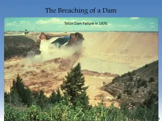
CONSIDER THE CASE OF THE SUDDEN REMOVAL, BY DESIGN OR ACCIDENT, OF A DAM FILLED WITH SEDIMENT Before removal
REMOVAL OF THE DAM CAUSES A CHANNEL TO INCISE INTO THE DEPOSIT After removal
AS THE CHANNEL INCISES, IT ALSO REMOVES SIDEWALL MATERIAL A first treatment of the morphodynamics of this process was given in Chapter 15.
EXNER EQUATION OF SEDIMENT CONTINUITY WITH SIDEWALL EROSION The formulation of Chapter 15 is reviewed here. Bb = channel bottom width, here assumed constant • b = bed elevation t = elevation of top of bank Qb = volume bedload transport rate Ss = sidewall slope (constant) p = porosity of the bed deposit s = streamwise distance t = time Bs = width of sidewall zone • s = volume rate of input per unit length of sediment from sidewalls s > 0 for a degrading channel, i.e. b/t < 0
EXNER EQUATION OF SEDIMENT CONTINUITY INCLUDING SIDEWALL EROSION contd. In Chapter 15, the relations of the previous slide were reduced to obtain the relation: or That is, when sidewall erosion accompanies degradation, the sidewall erosion suppresses (but does not stop) degradation and augments the downstream rate of increase of bed material load.
ADAPTATION TO THE PROBLEM OF CHANNEL INCISION SUBSEQUENT TO DAM REMOVAL: THE DREAM MODELS Cui et al. (in press-a, in press-b) have adapted the formulation of the previous two slides to describe the morphodynamics of dam removal. These are embodied in the DREAM numerical models. These models have been used to simulate the morphodynamics subsequent to the removal of Saeltzer Dam, shown below. Saeltzer Dam, California before its removal in 2001.
THE DREAM MODELS Specify an initial top width Bbt and a minimum bottom width Bbm. If Bb > Bbm, the channel degrades and narrows without eroding its banks. If Bb = Bbm the channel degrades and erodes its sidewalls without further narrowing. But Bbm must be user-specified.
SUMMARY OF THE DREAM FORMULATION But how does the process really work? Some results from the experiments of Cantelli et al. (2004) follow.
EROSION PROCESS VIEWED FROM DOWNSTREAM Double-click on the image to see the video clip. rte-bookdamremfrontview.mpg: to run without relinking, download to same folder as PowerPoint presentations.
NOTE THE TRANSIENT PHENOMENON OF EROSIONAL NARROWING
EROSION PROCESS VIEWED FROM ABOVE Double-click on the image to see the video clip. rte-bookdamremtopview.mpg: to run without relinking, download to same folder as PowerPoint presentations.
EVOLUTION OF CENTERLINE PROFILE UPSTREAM (x < 9 m) AND DOWNSTREAM (x > 9 m) OF THE DAM Downstream aggradation Upstream degradation Former dam location
CHANNEL WIDTH EVOLUTION UPSTREAM OF THE DAM The dam is at x = 9 m downstream of sediment feed point. Note the pattern of rapid channel narrowing and degradation, followed by slow channel widening and degradation. The pattern is strongest near the dam.
REGIMES OF EROSIONAL NARROWING AND EROSIONAL WIDENING The dam is at x = 9 m downstream of sediment feed point. The cross-section is at x = 8.2 m downstream of the sediment feed point, or 0.8 m upstream of the dam.
CAN WE DESCRIBE THE MORPHODYNAMICS OF RAPID EROSIONAL NARROWING, FOLLOWED BY SLOW EROSIONAL WIDENING?
PART OF THE ANSWER COMES FROM ANOTHER SEEMINGLY UNRELATED SOURCE: AN EARTHFLOW IN PAPUA NEW GUINEA The earthflow is caused by the dumping of large amounts of waste rock from the Porgera Gold Mine, Papua New Guinea.
THE EARTHFLOW CONSTRICTS THE KAIYA RIVER AGAINST A VALLEY WALL The Kaiya River must somehow “eat” all the sediment delivered to it by the earthflow. Kaiya River earthflow
THE DELTA OF THE UPSTREAM KAIYA RIVER IS DAMMED BY THE EARTHFLOW The delta captures all of the load from upstream, so downstream the Kaiya River eats only earthflow sediment earthflow
THE EARTHFLOW ELONGATES ALONG THE KAIYA RIVER, SO MAXIMIZING “DIGESTION” OF ITS SEDIMENT A downstream constriction (temporarily?) limits the propagation of the earthflow.
THE VIEW FROM THE AIR Kaiya River The earthflow encroaches on the river, reducing width, increasing bed shear stress and increasing the ability of the river to eat sediment!
THE BASIS FOR THE SEDIMENT DIGESTER MODEL (Parker, 2004) • The earthflow narrows the channel, so increasing the sidewall shear stress and the ability of the river flow to erode away the delivered material. • The earthflow elongates parallel to the channel until it is of sufficient length to be “digested” completely by the river. • This is a case of depositional narrowing!!!
GEOMETRY H = flow depth n = transverse coordinate nb = Bb = position of bank toe Bw = width of wetted bank nw = Bb + Bw = position of top of wetted bank Ss = slope of sidewall (const.) b = elevation of bed = volume sediment input per unit streamwise width from earthflow • The river flow is into the page. • The channel cross-section is assumed to be trapezoidal. • H/Bb << 1. • Streamwise shear stress on the bed region = bsb = constant in n • Streamwise shear stress on the submerged bank region = bss = bsb = constant • in n, < 1. • The flow is approximated using the normal flow assumption.
/t(sediment in bed region) transverse input from wetted bank region differential steamwise transport EXNER EQUATION OF SEDIMENT BALANCE ON THE BED REGION Local form of Exner: where qbs and qbn are the streamwise and transverse volume bedload transport rates per unit width. Integrate on bed region with qbs = qbss, qbn = 0;
transverse input from earthflow differential steamwise transport /t(sediment in wetted bank region) transverse output to bed region EXNER EQUATION OF SEDIMENT BALANCE ON WETTED BANK REGION Integrate local form of Exner on wetted bank region with region with: qbs = qbss for nb < n < nb + Bw qbn = - at n = nt where q denotes the volume rate of supply of sediment per unit length from the earthflow Geometric relation: Result:
EQUATION FOR EVOLUTION OF BOTTOM WIDTH Eliminate b/t between and to obtain Note that there are two evolution equations for two quantities, channel bottom elevation b and channel bottom width Bb. To close the relations we need to have forms for qbsb, qbss and . The parameter is specified by the motion of the earthflow.
FLOW HYDRAULICS Flow momentum balance: where S = streamwise slope and Bw = H/Ss, Flow mass balance Manning-Strickler resistance relation Here ks = roughness height, D = grain size, nk = o(1) constant. Reduce under the condition H/Bs << 1 to get:
Shields number on bed region: where R = (s/ - 1) 1.65. Shields number on bank region: Streamwise volume bedload transport rate per unit width on bed and bank regions is qbsb and qbss, respectively: where s = 11.2 and c* denotes a critical Shields stress, BEDLOAD TRANSPORT CLOSURE RELATIONS (Parker, 1979 fit to relation of Einstein, 1950). Transverse volume bedload transport rate per unit width on the sidewall region is qbns, where n is an order-one constant and from Parker and Andrews (1986),
SUMMARY OF THE SEDIMENT DIGESTER Equation for evolution of bed elevation Equation for evolution of bottom width The earthflow encroaches on the channel Hydraulic relations Sediment transport relations As the channel narrows the Shields number increases A higher Shields number gives higher local streamwise and transverse sediment transport rates. Higher local streamwise and transverse sediment transport rates counteract channel narrowing
EQUILIBRIUM CHANNEL Equilibrium channels that transport bedload without eroding their banks can be created in the laboratory (Parker, 1979). The image below shows such a channel (after the water has been turned off). The image is from experiments conducted by J. Pitlick and J. Marr at St. Anthony Falls Laboratoty, University of Minnesota.
EQUILIBRIUM CHANNEL SOLUTION As long as < 1, the formulation allows for an equilibrium channel without widening or narrowing as a special case (without input from an earthflow). Choose bed shear stress so that bank shear stress = critical value Streamwise sediment transport on wetted bank region = 0 Transverse sediment transport on wetted bank region = 0 Total bedload transport rate Three equations; if any two of Qw, S, H, Qb and Bb are specified, the other three can be computed!!
ADAPTATION OF THE SEDIMENT DIGESTER FOR EROSIONAL NARROWING • As the channel incises, it leaves exposed sidewalls below a top surface t. • Sidewall sediment is eroded freely into the channel, without the • external forcing of the sediment digester. • Bb now denotes channel bottom half-width • Bs denotes the sidewall width of one side from channel bottom to top • surface. • The channel is assumed to be symmetric, as illustrated below.
INTEGRAL SEDIMENT BALANCE FOR THE BED AND SIDEWALL REGIONS On the bed region, integrate Exner from n = 0 to n = nb = Bb to get On the sidewall region, integrate Exner from n = nb to n = nt under the conditions that streamwise sediment transport vanishes over any region not covered with water, and transverse sediment transport vanishes at n = nt
INTEGRATION FOR SIDEWALL REGION Upon integration it is found that or reducing with sediment balance for the bed region,
INTEGRAL SEDIMENT BALANCE: SIDEWALL REGION For the minute neglect the indicated terms: The equation can then be rewritten in the form: As the channel degrades i.e. b/t < 0, sidewall material is delivered to the channel. Erosional narrowing, i.e. Bb/t < 0 suppresses the delivery of sidewall material to the channel.
Auxiliary streamwise terms This term always causes widening whenever it is nonzero. INTERPRETATION OF TERMS IN RELATION FOR EVOLUTION OF HALF-WIDTH This term causes narrowing whenever sediment transport is increasing in the streamwise direction. But this is exactly what we expect immediately upstream of a dam just after removal: downward concave long profile!
REDUCTION FOR CRITICAL CONDITION FOR INCEPTION OF EROSIONAL NARROWING Where NS and NB are order-one parameters, Narrows if slope increases downstream Either way Widens At point of width minimum Bb/s = 0
REDUCTION FOR CRITICAL CONDITION FOR INCEPTION OF EROSIONAL NARROWING contd. Where Ns and Nb are order-one parameters, After some reduction, where M is another order-one parameter. That is, erosional narrowing can be expected if the long profile of the river is sufficiently downward concave, precisely the condition to be expected immediately after dam removal!
NUMERICAL MODELING OF THE MORPHODYNAMICS OF EROSIONAL NARROWING AND WIDENING Wong et al. (2004) used the formulation given in this chapter to numerically model one of the experiments of Cantelli et al. (2004). The code will eventually be made available in this e-book. Meanwhile, some numerical results are given in the next two slides. The reasonable agreement was obtained with a minimum of parameter fitting.
COMPARISON OF NUMERICAL MODEL WITH EXP. 5 OF CANTELLI et al. (2004): EVOLUTION OF LONG PROFILE Calculated and measured long profile 1200 seconds after commencement of experiment.
COMPARISON OF NUMERICAL MODEL WITH EXP. 5 OF CANTELLI et al. (2004): EVOLUTION OF CHANNEL WIDTH Calculated and measured water surface width 0.9 m upstream of original position of dam.
1D SEDIMENT TRANSPORT MORPHODYNAMICS with applications to RIVERS AND TURBIDITY CURRENTS REFERENCES FOR CHAPTER 31 Cantelli, C. Paola and G. Parker, 2004, Experiments on upstream-migrating erosional narrowing and widening of an incisional channel caused by dam removal, Water Resources Research, 40(3), doi:10.1029/2003WR002940. Cui, ,Y., Parker, G., Braudrick, C., Dietrich, W. E. and Cluer, B., in press-a, Dam Removal Express Assessment Models (DREAM). Part 1: Model development and validation, Journal of Hydraulic Research, preprint downloadable at: http://cee.uiuc.edu/people/parkerg/preprints.htm . Cui, Y., Braudrick, C., Dietrich, W.E., Cluer, B., and Parker, G, in press-b, Dam Removal Express Assessment Models (DREAM). Part 2: Sample runs/sensitivity tests, Journal of Hydraulic Research, preprint downloadable at: http://cee.uiuc.edu/people/parkerg/preprints.htm . Einstein, H. A., 1950, The Bed-load Function for Sediment Transportation in Open Channel Flows, Technical Bulletin 1026, U.S. Dept. of the Army, Soil Conservation Service. Parker, G., 1979, Hydraulic geometry of active gravel rivers, Journal of Hydraulic Engineering, 105(9), 1185‑1201. Parker, G., 2004, The sediment digester, Internal Memorandum 117, St. Anthony Falls Laboratory, University of Minnesota, 17 p, downloadable at: http://cee.uiuc.edu/people/parkerg/reports.htm . Wong, M., Cantelli, A., Paola, C. and Parker, G., 2004, Erosional narrowing after dam removal: theory and numerical model, Proceedings, ASCE World Water and Environmental Resources 2004 Congress, Salt Lake City, June 27-July 1, 10 p., reprint available at: http://cee.uiuc.edu/people/parkerg/conference_reprints.htm .