Download
1 / 66
660 likes | 776 Views
AMS Superconducting Magnet Flight Operations April 2007 Steve Harrison Scientific Magnetics. All operating conditions of the magnet system are defined in terms of States, Procedures, and Events. State A stable condition for the magnet. Procedure For transition between states.

E N D
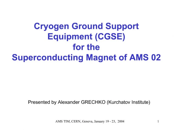
AMS Superconducting MagnetFlight Operations • April 2007 • Steve HarrisonScientific Magnetics
All operating conditions of the magnet system are defined in terms of States, Procedures, and Events. State A stable condition for the magnet Procedure For transition between states Event External occurrence triggers a change of state or procedure
Including all ground operations, a total of 17 states (A to Q) 40 procedures (1 to 40) 10 events have been identified.
In flight, only a small subset of these will normally be used.
If power and communications are lost for a sufficiently long period, the magnet will be discharged under automatic control.
However unlikely, a quench can – in principle – occur when the magnet is at field or if the field is changing. An automatic recovery procedure re-cools the magnet ready for re-charging.
Fill/drain valve Warm helium system for valve actuation Pressure switch Pilot valves (lead disconnects) Helium bus (6 bar) Shut-off valves Vent valves Pressure regulator Helium gas bottle Pilot valves (cryogenic valves) Pilot valves (warm latching valves)
Regulator and valves reduce the pressure from 200 bar (bottle) to 6 bar (bus). Helium bus (6 bar) Regulator (Stanford Mu) Electrically actuated valves (Moog) Gas bottle (Ardé)
Pilots connect the valve actuators to 6 bar (for operation) or vent. Helium bus (6 bar) Valve actuator Vent
Warm latching valves require two pilots: one to open and one to shut. Open Shut
With 10 warm latching valves a total of 20 pilot valves are required.
The cryogenic valves and current lead disconnects are Normally Closed, so require only one pilot valve to operate.
To close the valve, the actuating gas is vented to the PVVV, then to space via the electrical valve quartet DV20.
Magnet Process and Instrumentation Diagram (P&ID). State M – before launch.
Magnet Process and Instrumentation Diagram (P&ID). State M – before launch.
Magnet Process and Instrumentation Diagram (P&ID). State M – before launch.
Procedure 035 (1) “Open warm helium supply valves DV22”
Procedure 035 (2) “Open pilot valves DV65AO, DV65BO, DV65CO, DV65DO”
Procedure 035 (3) “Valves DV15A/B/C/D open”
Procedure 035 (4) “Close warm helium supply valves DV22”
Procedure 035 (5) “Open warm helium supply valves DV22”
Procedure 035 (6) “Open pilot valves DV61AO, DV61BO”
Procedure 035 (7) “Valves DV11A/B open”
Procedure 035 (8) “Open pilot valves DV66AO, DV66BO”
Procedure 035 (9) “Valves DV16A/B open”
Procedure 035 (10) “Open PVVV vent valves DV20”
Procedure 035 (11) “Close warm helium supply valves DV22”
Procedure 036 (1) “Open warm helium supply valves DV22”
Procedure 036 (2) “Power thermo-mechanical pump TMP01”
Procedure 036 (3) “Open pilot valves DV56A, DV56B”
Procedure 036 (4) “Valves DV06A and DV06B open” “Current lead cooling starts”
Procedure 036 (5) “Open pilot valves DV21A/B/C/D”
Procedure 036 (6) “Current lead disconnects close”
Procedure 036 (7) “Turn off cryocoolers” “Power persistent switch heater” “Begin charging magnet using CAB”
Procedure 036 (8) “Turn off persistent switch heater” “Complete charging magnet using CAB” “Allow persistent switch to close” “Power down CAB” “Turn on cryocoolers”
Procedure 036 (9) “Turn off thermo-mechanical pump TMP01” “Current lead cooling stops”
Procedure 036 (10) “Close pilot valves DV21A/B/C/D” “Current lead disconnects open”
Procedure 036 (11) “Close pilot valves DV56A, DV56B” “Valves DV06A/B shut”
Procedure 036 (12) “Close warm helium supply valves DV22” States N, O, and P – on orbit.
Procedure 037 (1) “Open warm helium supply valves DV22”
Procedure 037 (2) “Power thermo-mechanical pump TMP01”
Procedure 037 (3) “Open pilot valves DV56A, DV56B”
Procedure 037 (4) “Valves DV06A and DV06B open” “Current lead cooling starts”
Procedure 037 (5) “Open pilot valves DV21A/B/C/D” “Current lead disconnects close” “Wait for leads to cool”