Download
1 / 46
540 likes | 979 Views
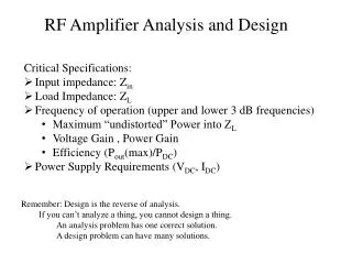
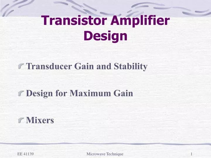
Transistor Amplifier Design. Transducer Gain and Stability Design for Maximum Gain Mixers. Transducer Gain and Stability. a single stage transistor amplifier with matching networks at the input and output terminals of the transistor is shown below:. Transducer Gain and Stability.

E N D
Transistor Amplifier Design • Transducer Gain and Stability • Design for Maximum Gain • Mixers Microwave Technique
Transducer Gain and Stability • a single stage transistor amplifier with matching networks at the input and output terminals of the transistor is shown below: Microwave Technique
Transducer Gain and Stability • the reflection coefficient on the input side of the transistor is given by Microwave Technique
Transducer Gain and Stability • similarly, the reflection coefficient on the output side of the transitor is given by Microwave Technique
Transducer Gain and Stability • we can define a transducer gain as the ratio of the power delivered to the load to the power available from the source Microwave Technique
Transducer Gain and Stability Microwave Technique
Transducer Gain and Stability • the power available from the source is the maximum power that can be delivered to the network, i.e., Microwave Technique
Transducer Gain and Stability • therefore, the transducer gain is given by Microwave Technique
Transducer Gain and Stability • is the gain of the input matching network, is the gain of the amplifier and is the gain of the output matching network Microwave Technique
Transducer Gain and Stability • the transistor is said to be unilateral when = 0 or is very small, the unilateral transducer gain reduces to Microwave Technique
Transducer Gain and Stability • note that the overall gain is dictated by the gain due to the matching networks as well as the gain of the transistor • the network is said to be unconditionally stable if and for all passive source and load impedance Microwave Technique
Transducer Gain and Stability • Note that both and depends on and , respectively • we need to find the range that these conditions are satisfied and Microwave Technique
Transducer Gain and Stability • for a unilateral device, these conditions reduces to and • let us consider the first condition that Microwave Technique
Transducer Gain and Stability • here D is the determinant of the scattering matrix Microwave Technique
Transducer Gain and Stability • if we square both sides of the above equation Microwave Technique
Transducer Gain and Stability • our goal here is to derive an expression for Microwave Technique
Transducer Gain and Stability • to simplify our discussion, let us consider the expression that • |a|2 Microwave Technique
Transducer Gain and Stability • If we set , the above equation for can be written as Microwave Technique
Transducer Gain and Stability • in deriving the above result, we make use of and Microwave Technique
Transducer Gain and Stability • the above equation written in the form represents a circle on a complex plane with the center at and a radius with • similar result can be obtained for with the roles of and interchanged Microwave Technique
Transducer Gain and Stability • to check the stable region, let us consider the diagram below: Microwave Technique
Transducer Gain and Stability • since we obtained the above circle at , the possible stable region is either outside or inside this circle with the additional constraint that Microwave Technique
Transducer Gain and Stability • consider a matched load so that is zero which leads to If ,therefore , is in the stable condition Microwave Technique
Transducer Gain and Stability • therefore, the stable region is defined as the shaded region below: Microwave Technique
Transducer Gain and Stability • on the other hand, if , it implies that and the point =0 is in the unstable region Microwave Technique
Transducer Gain and Stability • the stable region is therefore given by the shaded region below for Microwave Technique
Transducer Gain and Stability • similar discussions can be applied to the input stability circle • mathematically, the amplifier will be unconditionally stable if the following necessary and sufficient conditions are met • and Microwave Technique
Design for Maximum Gain (Conjugate Matching) • maximum power transfer from the input matching network to the transistor occurs when while the maximum power transfer from the transistor to the output matching network occurs at Microwave Technique
Design for Maximum Gain (Conjugate Matching) • for a lossless matching sections, the maximum overall gain will be given by Microwave Technique
Design for Maximum Gain (Conjugate Matching) • we need to determine and ; for maximum power transfer, they are given by Microwave Technique
Design for Maximum Gain (Conjugate Matching) • with the above expression, we can determine either or by first eliminating one of them Microwave Technique
Design for Maximum Gain (Conjugate Matching) • taking the complex conjugate of the second equation and substituting the result into the first equation, we obtain Microwave Technique
Design for Maximum Gain (Conjugate Matching) • The solution is • Where Microwave Technique
Design for Maximum Gain (Conjugate Matching) • For , the solutions are identical to those of except that the roles of and are interchanged • for the unilateral case = * and = * Microwave Technique
Mixers • A mixer uses the nonlinearity of a diode to generate an output spectrum consisting of the sum and difference frequencies of two input signals. • In a receiver application, a low-level RF signal and an RF local oscillator (LO) signal are mixed together to produce an intermediate frequency (IF) Microwave Technique
Mixers • and a much higher frequency • the signal will pass through a low-pass filter to get rid of the higher frequency • down-conversion in a heterodyne receiver Microwave Technique
Mixers • up-conversion in a transmitter • the IF signal usually has a frequency between 10 and 100 MHz, and can be amplified with a low-noise amplifer Microwave Technique
Mixers • this is called a heterodyne receiver, and is useful because it has much better sensitivity and noise characteristics than the direct detection scheme • it also has the advantage of being able to tune over a band by simply changing the LO frequency, without the need for a high-gain, wideband RF amplifier Microwave Technique
Balanced Mixer • a balanced mixer combines two or more identical single-ended mixers with a 3dB hybrid junction (90o or 180o) to give either better input SWR or better RF/LO isolation Microwave Technique
Balanced Mixer • the mixer circuit consists of two single-ended mixers with matched characteristics, driven with a 3dB coupler Microwave Technique
Balanced Mixer • consider that a small random noise voltage , vn(t), is superimposed on the local oscillator signal, the first order term of this noise voltage will be cancelled in this balanced mixer • , , Microwave Technique
Balanced Mixer • we have a 90o hybrid so that the voltages across the two diodes are Microwave Technique
Balanced Mixer • the V-I characteristic of the diode is given by • note that the quadratic term of the will give rise to the desire mixer product and the directions of Diode 1 and Diode 2 are reversed, we have Microwave Technique
Balanced Mixer • the diode currents, after passing through a low-pass filter, consist of a DC term, the noise term and the IF term: Microwave Technique
Balanced Mixer • summing the two currents, we have • therefore, the first order term of the noise is eliminated Microwave Technique
Tutorial 5 • Design a stop-band filter by incorporating a photonic bandgap structure on the microstrip line. The stop-band frequency is dictated by the periodicity of the PBG unit-cell. Be creative in generating the shape of the PBG. First check your design by simulations using Ensemble. Fabricate your design and compare your results with simulations. Microwave Technique