Download
1 / 59
610 likes | 723 Views
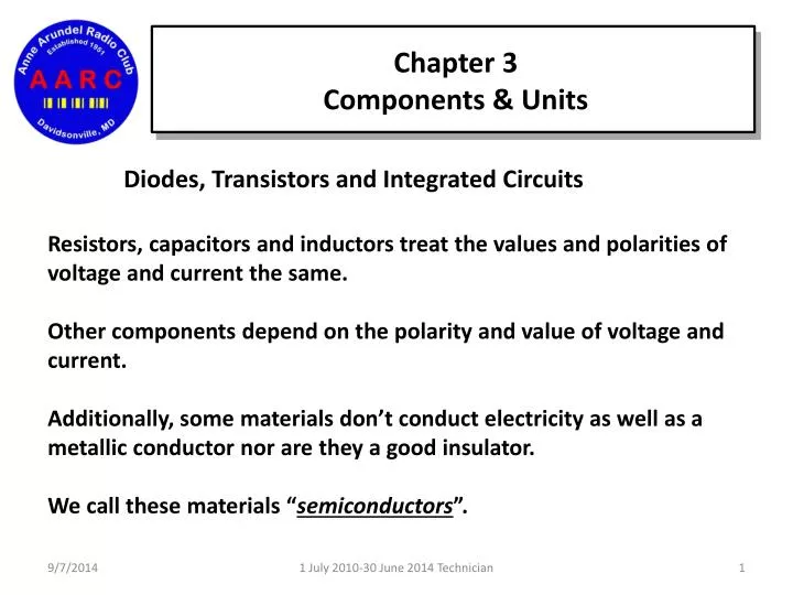
Chapter 3 Components & Units. Diodes, Transistors and Integrated Circuits. Resistors, capacitors and inductors treat the values and polarities of voltage and current the same. Other components depend on the polarity and value of voltage and current.

E N D
Chapter 3 Components & Units Diodes, Transistors and Integrated Circuits Resistors, capacitors and inductors treat the values and polarities of voltage and current the same. Other components depend on the polarity and value of voltage and current. Additionally, some materials don’t conduct electricity as well as a metallic conductor nor are they a good insulator. We call these materials “semiconductors”. 1 July 2010-30 June 2014 Technician
Chapter 3 Components & Units Diodes, Transistors and Integrated Circuits Some semiconductors, such as silicon, add small amounts of certain impurities. This is called “doping” and it changes the ability of semiconductors to conduct current. Depending on the type of impurities used, the result is “N-type” or “P-type” materials. 1 July 2010-30 June 2014 Technician
Chapter 3 Components & Units Diodes, Transistors and Integrated Circuits When N-type and P-type materials are in contact with each other, the result is a “PN Junction” that conducts better in one direction than the other. Junction Field + P-Type N-Type Anode Cathode 1 July 2010-30 June 2014 Technician
Chapter 3 Components & Units Diodes, Transistors and Integrated Circuits A semiconductor that only allows current to flow in one direction is called a “diode”. Heavy duty or large diodes are called “rectifiers”. Used in power supplies and power conversion units. An ac voltage applied to a diode results in a unidirectional, varying or pulsing dc current. 1 July 2010-30 June 2014 Technician
Chapter 3 Components & Units Diodes, Transistors and Integrated Circuits A diode has two electrodes – An “Anode” and a “Cathode”. The cathode is indicated by a stripe. Current flows from anode to cathode. Cathode Anode 1 July 2010-30 June 2014 Technician
Chapter 3 Components & Units A special type of diode gives off light when current flows through it. These are called “Light Emitting Diodes” or “LEDs” The material from which the LED is made determines the color of light that is emitted. LEDs are most often used as visual indicators. Because LEDs require less power, they are used in place of incandescent indicator lamps. 1 July 2010-30 June 2014 Technician
Chapter 3 Components & Units Transistors are made from patterns of N- and P-type material. The patterns form structures that allow the transistor to use small voltages and currents to control larger ones. With the appropriate external circuit and a source of power, transistors can amplify or switch voltages and currents. Using small signals to control larger signals is called “gain”. 1 July 2010-30 June 2014 Technician
Chapter 3 Components & Units • There are two common types of transistors: • Bipolar Junction Transistors (BJT) • Field-effect Transistors (FET) 1 July 2010-30 June 2014 Technician
Chapter 3 Components & Units • The BJT is made from three alternating layers of N- and P-type materials and there are types based on the layer arrangement of the materials. • NPN • PNP C • The electrodes are called the: • “base”, • “emitter” and • “collector”. B E C B E 1 July 2010-30 June 2014 Technician
Chapter 3 Components & Units The FET is constructed as a conducting path or channel of N- or P-type material. The ends of the channel form the “source” and “drain” electrodes. The “gate” electrode is used to control current through the channel. 1 July 2010-30 June 2014 Technician
Chapter 3 Components & Units An integrated circuit (IC or “chip”) is made of many components connected together and packaged as a single component. = 1 July 2010-30 June 2014 Technician
Chapter 3 Components & Units A brief history of how we got here 3rd Gen 2nd Gen Small = <100 transistors Med = 100-1000 1st Gen 1 July 2010-30 June 2014 Technician
Chapter 3 Components & Units 5th Gen 4th Gen Over 1 million transistors Large = 1000-10k transistors VL = 10k-1M transistors 1 July 2010-30 June 2014 Technician
Chapter 3 Components & Units The trend continues largely unabated, with chips introduced in 2007 containing tens of billions of transistors. 1 July 2010-30 June 2014 Technician
Chapter 3 Components & Units Protective Components Protective components are used to prevent equipment damage or safety hazards such as fire or electrical shocks caused by equipment malfunction. Fuses interrupt excessive current flow by belting a short length of metal. When the metal melts the current path is broken and power is removed from the circuits affected. 1 July 2010-30 June 2014 Technician
Chapter 3 Components & Units Protective Components Circuit breakers are automatically-operated electrical switches designed to protect an electrical circuit from damage caused by overload or short circuit. When it detects a fault condition it “trips” and immediately discontinues electrical flow. Unlike a fuse, which operates once and then has to be replaced, a circuit breaker can be reset (either manually or automatically) to resume normal operation. 1 July 2010-30 June 2014 Technician
Chapter 3 Components & Units Fuses 1 July 2010-30 June 2014 Technician
Chapter 3 Components & Units Circuit Breakers GFCI Circuit Breaker Circuit Breaker Panel 1 July 2010-30 June 2014 Technician
Chapter 3 Components & Units Use properly sized fuses and circuit breakers. Never replace a fuse or circuit breaker with one of a larger current rating. Fix the problem instead of trying to work around the problem. 1 July 2010-30 June 2014 Technician
Chapter 3 Components & Units “Surge protectors”limit temporary voltage transients above normal ranges. The effectively become a resistor and dissipate the energy as heat. “Lightning arrestors” perform a similar function but involving the much higher voltages and currents of a lightning strike. 1 July 2010-30 June 2014 Technician
Chapter 3 Components & Units Circuit Gatekeepers • Switches and relays are simple components that control current through a circuit by connecting and disconnecting the paths that current can follow. • Opening the circuit interrupts the flow of current. • Closing the circuit allows the current to flow. • A switch is operated manually while a relay is a switch that is controlled by an electromagnet. 1 July 2010-30 June 2014 Technician
Chapter 3 Components & Units • Switches and relays are described by their number of “poles” and “throws”. • Each pole controls the path of one current. • A “single pole” (SP) switch controls a single current path. • A “double pole” (DP) switch controls two separate current paths. 1 July 2010-30 June 2014 Technician
Chapter 3 Components & Units • Each throw refers to a different path for the current. • A “double throw” (DT) switch can route current through either of two paths while a “single throw” (ST) switch can only open or close a single path. • The combination of poles and throws describes the switch. • SPST – Single pole, single throw • DPST – Double pole, single throw • DPDT – Double pole, double throw 1 July 2010-30 June 2014 Technician
Chapter 3 Components & Units Indicators and displays are important components for radio equipment. An “indicator” usually tells you if something is on or off. Meters provide information as a value in the form of numbers or on a numeric scale. Indicators and meters are often combined in a display on the front panels of many radios. 1 July 2010-30 June 2014 Technician
Chapter 3 Components & Units Schematics and Component Symbols In order to describe complicated circuits, engineers have developed the “schematic diagram” or simply “schematic”. Schematics create a visual description of a circuit by using standardized symbols for electrical components called “circuit symbols”. 1 July 2010-30 June 2014 Technician
Chapter 3 Components & Units Schematics and Component Symbols A schematic does not illustrate the physical layout of a circuit. It only shows how the components are connected electrically. The lines drawn between components represent the electrical connection. Each line does not necessarily correspond to a physical wire – it just indicates that an electrical connection exists. 1 July 2010-30 June 2014 Technician
Chapter 3 Components & Units • Each component in a schematic is assigned a unique designator. • Resistors are designated with “R” • Capacitors are designated with “C” • Inductors with “L” • Diodes with “D” • Transistors with “Q” • The first resistor used is designated R1; the second is R2; the third is R3, etc. 1 July 2010-30 June 2014 Technician
Chapter 3 Components & Units 1 July 2010-30 June 2014 Technician
Chapter 3 Components & Units Symbols you need to know Anode + Multi Cell Battery - Diode Cathode Capacitor Single Pole Single Throw (SPST) Switch 1 July 2010-30 June 2014 Technician
Chapter 3 Components & Units Antenna Fixed Resistor LAMP Adjustable Resistor or Potentiometer “Pot” Transformer Variable Inductor 1 July 2010-30 June 2014 Technician
Chapter 3 Components & Units What does component 1 represent? A resistor or a fixed resistor 1 July 2010-30 June 2014 Technician
Chapter 3 Components & Units What does component 2 represent? A transistor (NPN) 1 July 2010-30 June 2014 Technician
Chapter 3 Components & Units What does component 3 represent? A lamp 1 July 2010-30 June 2014 Technician
Chapter 3 Components & Units What does component 1 represent? A battery or a multi-cell battery 1 July 2010-30 June 2014 Technician
Chapter 3 Components & Units What does component 6 represent? A capacitor or a fixed capacitor 1 July 2010-30 June 2014 Technician
Chapter 3 Components & Units What does component 8 represent? A light emitting diode 1 July 2010-30 June 2014 Technician
Chapter 3 Components & Units What does component 9 represent? A variable resistor 1 July 2010-30 June 2014 Technician
Chapter 3 Components & Units What does component 4 represent? A transformer 1 July 2010-30 June 2014 Technician
Chapter 3 Components & Units What does component 3 represent? A variable inductor 1 July 2010-30 June 2014 Technician
Chapter 3 Components & Units What does component 4 represent? An antenna 1 July 2010-30 June 2014 Technician
Chapter 3 Types of Radios & Radio Circuits We use block diagrams to describe the various states that comprise basic stages of radio transmitters and receivers. In the early days of radio, amateurs used a separate transmitter and receiver which shared an antenna. The operator used a switch to connect the transmitter to the antenna and then to the receiver to hear the other station’s response. 1 July 2010-30 June 2014 Technician
Chapter 3 Types of Radios & Radio Circuits A simple CW transmitter Power Amplifier The oscillator circuit generates a low-power signal with a steady frequency. The next stage of the transmitter is the “driver” which is an amplifying circuit that makes the signal stronger. The “power amplifier” increases the signal strength so other stations can hear the signal. The telegraph key turns the output signal on and off to create Morse code characters. Oscillator Driver Telegraph Key 1 July 2010-30 June 2014 Technician
Chapter 3 Types of Radios & Radio Circuits • “Filters” are circuits that perform very important functions in radio (e.g., reject unwanted signals and noise). • “Passive filters” are made from resistors, inductors and capacitors. Tuned circuits are common examples. • “Active filters” are circuits that contain amplifiers. Reducing a signal’s strength is called “attenuation”. A filter circuit rejects unwanted signals by attenuating them. 1 July 2010-30 June 2014 Technician
Chapter 3 Types of Radios & Radio Circuits • The name of the filter describes what it does with respect to signals. • High-pass – a filter that attenuates signals below a specified cutoff frequency. Allows signals above the cutoff frequency to be heard. • Low-pass – A filter that allows signals below a specified cutoff frequency to be heard and rejects signals above the cutoff frequency. 1 July 2010-30 June 2014 Technician
Chapter 3 Types of Radios & Radio Circuits • Band-pass – a filter that rejects signals above and below specified cutoff frequencies. Allows signals between the cutoff frequencies to be heard. • Notch – opposite of the band-pass filter. It rejects signals between the cutoff frequencies and allows the frequencies above and below the cutoff frequencies to be heard.. 1 July 2010-30 June 2014 Technician
Chapter 3 Types of Radios & Radio Circuits “Modulation” is the process of combining data or voice signals with an RF signal. A circuit that performs the modulation function is called a “modulator”. When the modulator circuit does its job, the result is an RF signal that can be communicated via radio. 1 July 2010-30 June 2014 Technician
Chapter 3 Types of Radios & Radio Circuits “Mixers” are closely related to modulators. Both types of circuits combine signals with the intent of producing an output signal with a different frequency. The mixer combines two RF signals. It does not combine a data or voice signal with an RF signal. Mixers are used in transmitters and receivers to shift signal frequencies for various purposes. 1 July 2010-30 June 2014 Technician
Chapter 3 Types of Radios & Radio Circuits “Demodulators” are circuits that separates the data or voice from an RF signal. Several methods of demodulation can be used so demodulator is a general term that is applied to the many different types of circuits used for demodulation. “Detectors” are one category of demodulators. A detector converts a modulated RF signal directly into a data or voice signal. 1 July 2010-30 June 2014 Technician
Chapter 3 Types of Radios & Radio Circuits • “Product Detectors” detect CW and SSB signals by combining a signal at the frequency of the modulated signal’s RF carrier with the modulated signal itself. • For CW signals, the output of the product detector is an audio reproduction of the Morse code pattern. • For SSB signals, the output is the reproduced data or speech signal. 1 July 2010-30 June 2014 Technician
Chapter 3 Types of Radios & Radio Circuits A “frequency discriminator” or “discriminator” is used to recover information from an FM signal. A discriminator translates the variations of the FM signal’s frequency back to the original signal used to modulate the RF signal. 1 July 2010-30 June 2014 Technician