Download
1 / 4
40 likes | 159 Views
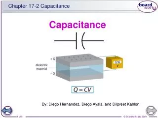
Capacitance Measurements. Using the Digital Multimeter. Capacitor Marking. Polyester Capacitors use a 3 digit code + letter. Marked in pF 1 st digit is the 1 st number in the value 2 nd digit is the 2 nd number in the value 3 rd digit is the multiplier power of 10

E N D
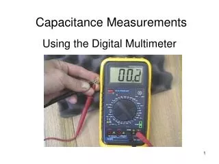
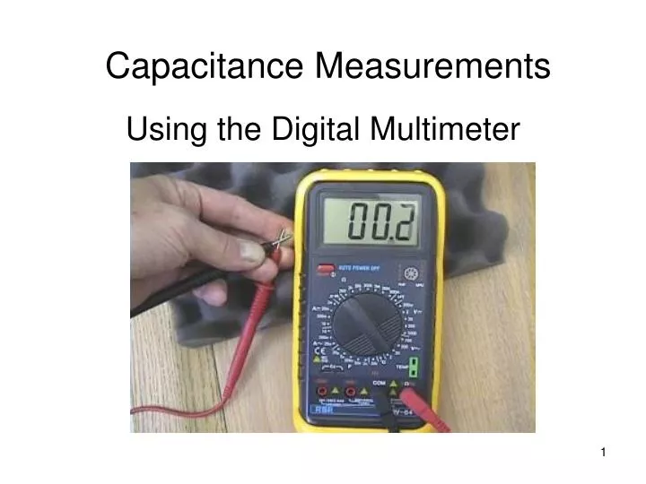
Capacitance Measurements Using the Digital Multimeter
Capacitor Marking Polyester Capacitors use a 3 digit code + letter. • Marked in pF • 1st digit is the 1st number in the value • 2nd digit is the 2nd number in the value • 3rd digit is the multiplier power of 10 • Think of this as the number of zeros in the value • The last letter is the torerance • J = ± 5%, K = ± 10%, M = ± 20% • There may be manufacturer’s codes before the 3 digit value code (2A in the top photo) Electrolytic Capacitors are marked on the body • The value and voltage are marked • the – bar indicates the negative lead, which must be connected to a point lower in voltage than the other lead on the capacitor.
Capacitor value measurement • Insert the capacitor leads into the Cx slots in the meter (yellow arrow). Many capacitor leads may not properly reach the internal meter terminals. Use the adapter (green arrow) that provides a better connection to the meter. (bottom right photo). • Take care. The adaptor tends to come apart. When it does, the metal prongs in the adapter fall out – they are not glued in place. The adapter can be reassembled. • Set the meter switch to somewhere in the F (Farad) range (red arrow).
Range Selection • Adjust the range for best accuracy without overflow. • n = nanoFarads (10-9F) • μ = microFarads (10-6F)