Download
1 / 40
400 likes | 736 Views
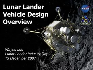
Trailblazer Lunar Transfer Vehicle Conceptual Design Overview. Robert L. Howard, Jr., Ph.D. Doctoral Dissertation, Aerospace Engineering University of Tennessee Space Institute. Introduction.

E N D
Trailblazer Lunar Transfer Vehicle Conceptual Design Overview Robert L. Howard, Jr., Ph.D. Doctoral Dissertation, Aerospace Engineering University of Tennessee Space Institute
Introduction • “I want them [NASA] to be constantly suggesting what the next frontier should be and making the case that that frontier is important to humankind. Without them making that case I think the level of support will diminish over time.” • Congressman Mel Watt, D-NC • The United States must return to the moon • Fulfill directives of National Aeronautics and Space Act, 1957 • Enable US commercial industries • Maintain US technological superiority and space leadership
Introduction How to Return Humans to the Moon – My Version • Small, trailblazing program (“Trailblazer”) • Commercial/International programs will follow after Trailblazer, but USA sets the initial pace • Establish human operational presence on the moon • Infrastructure development, critical studies of human factors, hardware, and operation concepts • Provide starting point for permanent occupation and utilization
Introduction Trailblazer LTV Mission Requirements and Constraints • Assume no heavy launch vehicle development • Available launch vehicles limited to STS, Delta and Atlas • Minimize the development of new space vehicles • Intelligent navigation systems with maximum possible versatility • Ability to receive ISS and STS support but requires neither • $3-6 billion increase in NASA annual budget for Trailblazer LTV activities • 5-10 year development timeline from concept to first crew landing • Ten year design lifetime • United States mission with limited to no foreign participation • Minimize ground operations support team
Lessons from the Past • Avoid Causes of Program Cancellation • Must be cognizant of threat of budget cuts • Must not rely on new super boosters • Must not use controversial vehicle configurations (i.e. HLR open-cockpit lander) • Must not rely on unproven use of in-situ resources • Must give credible mass estimates • Accurately consider delta-v requirements of orbital transfers • No Apollo-like massive budget increase
L1 used as staging area (outbound and inbound) L1 unstable, but low delta-v to maintain position Enables launches within limits of existing Earth launch vehicles Assumes 28.5-degree LEO inclination Cryogenic propellants used for LEO departure only, hypergolics used elsewhere Upgraded TDRSS at GEO and Lissajous L2 orbit for communications LTV spacecraft at L1 can also serve as relays Trajectory Overview
Crew Module Trailblazer LTV Spacecraft Overview • Propulsion Module 1 • Ascent Descent Vehicle • Aeroshell Module • Fuel Tanker • Propulsion Module 2
Infrastructure Development Mission 1 Infrastructure Development Mission 2 Infrastructure Development Mission 3 Fuel Prospecting Mission 1 Fuel Prospecting Mission 2 Fuel Prospecting Mission 3 Commercial Opportunities Mission 1 Commercial Opportunities Mission2 Trailblazer Missions OverviewEight Lunar Missions over Four Year Period LTV provides crew transport for these missions
Crew Module • Vehicle selection • Potential options: ISS module, Spacelab module, SpaceHab module, TransHab inflatable, X-38, Apollo, Gemini, unique design • X-38 selected (OSP potential alternate) • Atmosphere Management • Stored oxygen, nitrogen • Lithium hydroxide CO2 removal • Cabin Pressure • Driven by EVA considerations • 68 kPa, 28% O2, 72% N2 • Zero prebreathe time required
Crew Module • Water Supply • Partially closed system • 2 multifiltration loops • Loop 1: hand wash, dishwashing water • Loop 2: urine flush water • 2.1-day supply source stock doubles as secondary radiation shield • Backup to primary shield - located onboard PM1 • Recovery rate of 85% assumed • 68 kg open loop potable water
Crew Module • Radiation shield • CM operates 3-4 days prior to rendezvous with PM1 and must have shielding for crew • Sized to protect two 95th percentile adult males • Does not leave room for crew to move around while shielded • Requires CM to turn aft section towards radiation source • Crew Accommodations • Supports crew of 2 for 14.5 days • Limited cargo and medical provisions also required
Crew Module • Avionics • Sensors • SIGI GPS (2) • Star sensors (2) • Sun sensors (6) • Horizon sensors (2) • Laser rangefinders (6, three per docking port) • Flush Air Data System (used below Mach 3) • Autonomy • Deep Space One derived AutoNav, Remote Agent, and Mode Identification and Recovery AI systems
Crew Module • Avionics • Flight Computer • Radiation hardened Pentiums • Modern laptops (5) • Wireless network • All LTV flight software stored on all computers • Thermal • System sized based on vehicle power • Cabin air heat exchangers, coldplates, heat pumps, associated plumbing and valves, instruments and controls, fluids, and radiator • Two redundant loops feed into radiator or aft docking port • Radiator mounted on solar array wing underside, perpendicular to array surface (in shade when array tracks sun) • Uses existing X-38 tiles for Earth entry TPS and water as heat sink for entry thermal control (will not cause water to boil)
Crew Module • Docking • 2 ports: dorsal surface & behind aft propulsion unit • Dorsal port: docks with Shuttle, ADV, AM • Crew transfer, sized for transfer wearing EMU • Aft port: docks with PM1, PM2, FT • Propellant, power, thermal fluid transfer • Magnetic Docking Aid System (MDAS) • APAS docking mount with electromagnets on extendible booms • Significantly reduces docking impact loads and risks • Increases viability of automated, autonomous docking
Crew Module • Communications • 12 Mbps data rate (10 Mbps video, 2 Mbps telemetry) • 46 GHz U-band frequency used by CM, other LTV spacecraft, and future TDRSS • Short range RF antenna for space-to-space communication with nearby vehicles • 0.779 m antenna diameter (standard for all LTV spacecraft) • 2 satellite phones (e.g. Iridium) for low volume data transfer from entry through landing
Crew Module • Propulsion • Auxiliary Propulsion System (APS) • Single RS-72 hypergolic engine • Delta-v for L1 capture and deorbit • Mounted on propulsion frame behind CM • Attitude Control System (ACS) • 16 R-4D hypergolic thrusters (in use since Apollo) • Deadband of 10 degrees in roll, pitch, and yaw when not in free drift
Crew Module • Power • Supplied by lithium metal dry polymer electrolyte batteries (300 Wh/kg) • Triple Junction solar array • Developed from Deep Space One SCARLET array • Lenses concentrate sunlight onto GaInP/GaAs/Ge cells • 300 W/m2 power density • Two array wings, mounted on propulsion unit • Superior mass trade over fuel cells and flywheels; avoids boiloff and water dumping concerns with fuel cells
Propulsion Module 1 • Hypergolic spacecraft • Plays similar role to Apollo SM • Exception: does not provide cabin air • Spare PM1 located at L1 • Radiation protection • Primary radiation shield • Polyethylene (sandwiched between aluminum foil) shield, .3m thick • Requires LTV to position PM1 between crew and radiation source
Propulsion Module 1 • Avionics • Identical sensor models to counterparts on CM • GPS, laser rangefinders (docking), star sensors, sun sensors, horizon sensor, autonomous navigation, flight computers • Docking • 2 MDAS docking ports: forward and ventral aft • Fwd port: CM, PM2 • Aft port: AM, FT • Both ports contain fuel, power, and thermal fluid transfer conduits • MGS plates
Propulsion Module 1 • Thermal • Unlike CM, cannot use cabin air heat exchangers • Uses cold plates and heat pipes instead • Otherwise, similar to CM TCS • Communications identical to CM, except 384,400 km range • Power system similar to CM • Propulsion • 2 RS-72 and 16 R-4D engines • Refueled multiple times in LEO, L1, and LLO
Ascent Descent Vehicle • Lunar Lander • New design, though components derived from other vehicles • Open-cockpit lander not considered; TransHab-style inflatable used for cabin instead • Mass reduction critical • Last link in LEO to surface chain • Mass increases to ADV have greatest impact on cost
Ascent Descent Vehicle • Impact of surface base location on ADV design: polar site advantageous • Continuous access to surface possible • Altitude drift ~20 km (due to mascons; greater in other orbits) • Continuous access to L1 from orbit (important for CM/ADV rendezvous)
Ascent Descent Vehicle • Configuration • Crew Compartment • TransHab-derived inflatable • Space for EMU-suited astronauts • Flight controls, cargo, maintenance tools, life support systems, CM docking port, lunar egress hatch • Propulsion Unit • Propulsion systems, batteries, thermal, comm, nav systems, landing gear, FT docking port, ladder
Ascent Descent Vehicle • Systems • Life support: pressurizes for dockings; slowly depressurizes after separation from CM • MIMU replaces GPS • Clementine LIDAR for laser altimeter • Other systems similar to counterparts on other LTV spacecraft
Aeroshell Module • Heat shield for CM and PM1 • Human flight requires rapid transfer • Large energy dissipation for capture into Earth orbit • X-38 TPS inadequate to protect from entry heating • PM1 must also be protected • Vehicle dives into atmosphere, uses drag to slow to orbital velocity • Aerocapture thermally intense, but preferable due to need for short mission duration
Aeroshell Module • Need for separate module • Thicker TPS on CM/PM1 would push mass beyond limits of conventional ELVs as well as PM2 booster • Intense heating environment also likely to require ablative TPS • If TPS attached to LTV, entire LTV would have to land for extensive servicing, driving up cost • LTV will use separate, disposable module • Similar avionics, prop, power to other LTV spacecraft • Disposable solar array, radiator deployed from AM for CM/PM1/AM power and heat rejection
Aeroshell Module • Entry velocity 10.97 km/s, estimated by approximating orbit of correct energy, assuming a perigee of 100 km and atmospheric entry at 125 km • Assuming exit velocity of 7.93 km/s, perigee velocity found to be 9.35 km/s • Perigee altitude of 65.55 km • Temperature and maximum heating rate generally determine the TPS material (1812°C and 102.32 W/cm2) • Selected TPS Materials: SIRCA, AETB-12, FRSI, LI-900
Aeroshell Module • Docking • LTV must enter AM and secure itself to two APAS docking mounts • To avoid propulsive firings inside AM, magnetic docking system will be used • AM equipped with two passive APAS mechanisms • Upper forward interior – Crew Module • Lower aft interior – Propulsion Module 1 • Each APAS augmented with steel plates to receive electromagnets from magnetic docking systems onboard CM and PM1 • Following figures depict MGS capture sequence
Aeroshell Module LTV Preparing to Enter Aeroshell Module LTV Retraction into Aerocapture Module
Aeroshell Module LTV Positioning at Docking Mounts • LTV Docked with Aeroshell Module
Fuel Tanker • Refuels LTV spacecraft • Variation on PM1- 2x number of fuel tanks and no ventral docking port • Five FTs used for odd numbered expeditions, six for even and first • FT-M1: refuels ADV in LLO • FT-M1b: supplements FT-M1 in first and even missions • FT-M2: refuels CM, PM1 in LEO • FT-M3: refuels PM1 at L1 • FT-M4: refuels PM1 in LLO • FT-M5: refuels CM and PM1 at L1
Propulsion Module 2 • Modified Centaur or Delta 4-2 • Design assumes Single Engine Centaur • Additional batteries • Passive MDAS APAS (standard or AM-boost configuration) • Short range transmitter for LTV wireless network • No changes to existing Centaur/Delta Avionics
CM to L1 PM1/AM to L1 PM1-S/AM-S to L1 ADV to LLO FT-M1 to LLO FT-M3 to L1 FT-M4 to LLO FT-M5 to L1 Propulsion Module 2 Responsible for 8 payload/trajectory combinations:
LTV Mission Control • Responsible for LTV • Interfaces with, but not responsible for Earth launch vehicles: shuttle, Atlas, Delta • Interfaces with, but not responsible for Trailblazer lunar surface base • Responsibility to Trailblazer crew begins when they enter the CM, ceases when they exit the ADV, resumes when they reenter ADV, terminates when they exit the CM – crew transferred between 3 MCCs (shuttle, LTV, base, [ISS is a potential 4th])
Mission Control • Important points to consider that make LTV MCC different from Apollo, Shuttle, ISS MCC • LTV composed of various spacecraft in different locations (LEO, L1, LLO, Lunar Surface, transit) • 5-14 LTV spacecraft in space at any given time • LTV is a system of spacecraft in permanent flight • Crew may or may not be onboard during critical activities (orbital transfers, rendezvous, docking, refueling)
Mission Control • Single LTV FCR, with MPSR support • Console positions based around LTV functionality • Each position responsible for that function on multiple vehicles • 21 FCR console positions; somewhat analogous to Shuttle and ISS FCRs • Total of 145 console operators during fully staffed periods (including all shifts)
Mission Control • Console Configuration • 3 computer workstations, driving 12 monitors • Video and data directed to any screen • Audio directed to workstation speakers or DVIS • 10 printers shared in FCR and MPSR • 8 wall projector screens • LTV MCC located in JSC Building 30
Cost Estimation • Communications Network $820 M • Vehicle Development $22 B • Spacecraft Propellant $28 M • Launch Vehicles $15 B • Mission Operations $3 B • Total Program Costs $40 B
Discussion and Implications • Fundamental Question • Can human lunar transfer between Low Earth Orbit and Lunar surface be conducted with present launch vehicles, largely operational technology, and at a realistic funding level? • Yes. • Uses existing launch vehicles • Primarily existing technology • Less than $5 billion a year
Discussion and Implications • Much work remains to be done, but achievable with no significant breakthroughs required (does require some technology development) • Implications of Action or Inaction • History: Chinese Treasure Fleet • In Middle Ages, China had superior naval technology to Europe, but decided sea power was unimportant – result was Western domination


![B2B Transfer System for FAIR (Conceptual Design [1])](https://cdn5.slideserve.com/9608574/b2b-transfer-system-for-fair-conceptual-design-1-dt.jpg)
