Download
1 / 28
280 likes | 398 Views
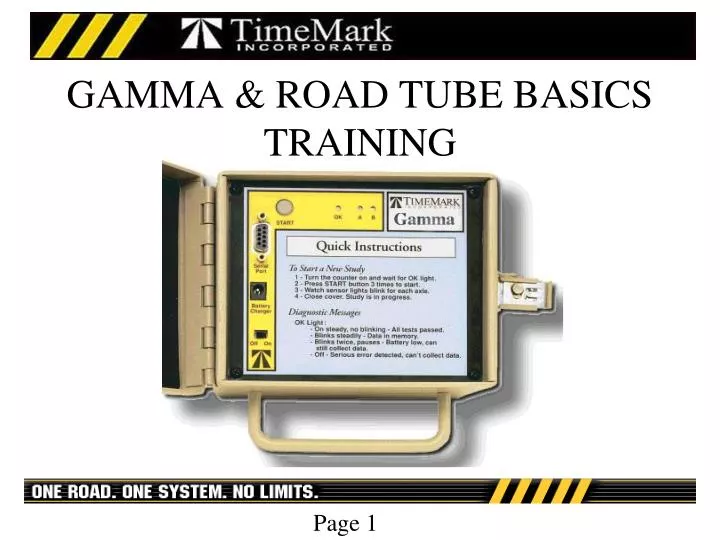
GAMMA & ROAD TUBE BASICS TRAINING. Overview of Gamma & Road Tube Basics Training. Introduction to Gamma counter Rules of Good data collection Road Tube basics Using the Gamma counter . The Gamma Counter. Simple operation Two tube counter Light weight (4.5 lbs)

E N D
Overview of Gamma & Road Tube Basics Training Introduction to Gamma counter Rules of Good data collection Road Tube basics Using the Gamma counter
The Gamma Counter Simple operation Two tube counter Light weight (4.5 lbs) 90 day battery life 2 MB of internal memory No programming necessary
Gamma Counter Operation Turn counter on Verify “OK” light is flashing Push “Start” button three times Verify “OK” light is solid Gamma is ready to collect data
Road Tube Basics Road tubes need to be of equal length Tubes should be placed a minimum of 300 ft away from a traffic control device to improve accuracy Tubes should be placed using a measured distance of 10 to 16 feet apart for high accuracy Tubes need to have the right amount of tension applied approximately 10% stretch Place counter in area that has constant speed flow
Layout 51: For the collection of Vehicle Counts, Classification, Speed, and Gap data on a bi-directional roadway.
Layout 52: For the collection of Vehicle Counts, Classification, Speed, and Gap data on a Single Direction Roadway.
Road Tube Basic Personal Supply List • Sledge hammer • Claw hammer • Gloves Safety vest • Tape Measure • Chalk
(2) End Plugs Supply list for a single layout 51/52 • (2) Figure 8 Clamps • (10) PK nails-2 1/2 inch • (2) Plate Clamps • Roll of Road Tape • (2) 6 inch pieces of webbing (2) 50 ft pieces of Road Tube
Pre-Layout procedures Grab one of the 50ft road tubes and an End Plug, and insert end plug into the end of the tube. Repeat the process with the other 50ft road tube. They slide in better if they are a little wet.
Layout procedures Grab one of the 50ft road tubes with end plug inserted and put on a plate clamp using a screw driver. Repeat the process with the other 50ft road tube
Pre-Layout procedures 2. Put a half twist in the large loop Forming a second loop. 1. Loop the Figure 8 over the hose. At the other end of one of the 50ft road tubes, put on a figure 8 clamp.
3. Pull the new loop over the end of the tube. 4. Slide the “Figure 8” you made down the tube. Pre-Layout procedures
Pre-Layout procedures This is what it should look like when finished. Put a figure 8 on the other tube also.
Layout procedures • Place the A hose down first • Place the hose to the left side of the anchor object as you are facing the road half the total distance you will use between hoses A and B • Always try to stay out of the travel lane when placing the hose Select the anchor point for the layout Pick something solid, like a fence post, or sign post Make sure the chain can’t be lifted over it
Layout Procedures • Lay out the hose as your walk back tothe near side of the roadway. Watch out for traffic. • Line up the road tube making sure that your hose will lay parallel to the vehicle axles as they travel across it. Place the end with the plate clamp on the far side of the road, 6-12 inches outside the white line. Nail in the plate clamp using 1 to 3 PK nails. Always keep some tension on the hose with your foot while working with it on the near side so a passing vehicle doesn’t pick it up.
Layout procedures Place the figure 8 clamp, 6-12 inches outside the white line, securing the hose on the near side of the roadway where the counter is placed. • Adjust the tension on the road tube by sliding the tube through the figure 8 Clamp.
Layout procedures Laying down the “B” hose Using a tape measure, hook it to the “A” tube, near the Figure 8 and measure 10 or 16 ft along the same side of the roadway. • Draw a “V” 6-12 inches outside the solid white line.
Layout procedures Cross the roadway ( take your supplies and hose with you) and repeat the process for hose “B”
Layout Procedures • Drive 1 to 3 PK nails through the plate clamp to fasten it to the roadway. Place the “B” tube plate clamp the same distance from the road edge as the “A” tube plate clamp. Line up the “B” tube with the “V” you drew on the roadway on the far side. • Lay out the hose as you cross back to the other side and line up the hose with the “V”on the near side.
Layout procedures Use a figure 8 clamp to secure the hose on the near side. Adjust the tension on the road tubes by sliding the tube through the figure 8 clamp.
Layout procedures • Repeat this process on the other road tube. In the middle of each lane at the center line, secure the road tube to the road with 6” piece of webbing and a PK nail. Loop webbing over road tube • Place a piece of 6” tape on both tubes in the middle of the lane. Helps prevent hose slap, roll, and echoes
Starting Counter Turn Counter On Verify “OK” light is flashing Push “Start” button three times Verify “OK” light is solid As counter faces the road way tilt counter back towards you, with handle pointing down.. Plug in the hose to the left “A” hose nipple Plug in the hose to the right “B” hose nipple • Verify a few axle hits by by watching “A” and “B” lights. If the counter appears to go dead press and hold the “start” button one time and it will return to monitor mode for four minutes.
Securing the counter • Wrap the chain securely around the anchor point and through the handle • Secure with lock
Congratulations!You have successfully laid out the Gamma Counter
Picking up the counter UN-lock the counter and open the lid Wake up the counter by holding down the start button to verify that the counter is still collecting. Turn the counter “off”
The Gamma counter is now ready to be downloaded. Road Tube Study Complete: Contact your TimeMark counter consultant at 1-800-755-5882 for instructions