Download
1 / 55
550 likes | 676 Views
NT1210 Introduction to Networking. Unit 5: Chapter 5, Ethernet LANs. 1. Objectives. Identify the major needs and stakeholders for computer networks and network applications. Identify the classifications of networks and how they are applied to various types of enterprises.

E N D
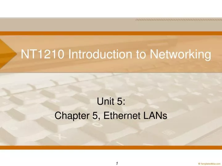
NT1210 Introduction to Networking Unit 5: Chapter 5, Ethernet LANs 1
Objectives • Identify the major needs and stakeholders for computer networks and network applications. • Identify the classifications of networks and how they are applied to various types of enterprises. • Explain the functionality and use of typical network protocols. • Analyze network components and their primary functions in a typical data network from both logical and physical perspectives. 2
Objectives • Differentiate among major types of LAN and WAN technologies and specifications and determine how each is used in a data network. • Explain basic security requirements for networks. • Install a network (wired or wireless), applying all necessary configurations to enable desired connectivity and controls. • Use network tools to monitor protocols and traffic characteristics. • Use preferred techniques and necessary tools to troubleshoot common network problems. 3
Objectives • Define Ethernet LAN concepts. • Evaluate the advantages and disadvantages of Ethernet technology in LANs. • Analyze the advantages of using Layer 2 devices to segment LANs. • Troubleshoot wired LANs for connectivity and performance. 4
Defining Ethernet LANs • Ethernet: Originally developed as LAN technology • Connect end-user devices in one site with devices relatively close by • Each LAN site connects to WAN via router • Ethernet standards kept growing to support faster speeds and longer cabling distances • Modern Ethernet networks might be LANs or WANs • Companies generally own their own LANs • WANs lease capacity to customers (e.g., ISPs, Telcos) 5
Defining Ethernet LANs: LAN vs. WAN Many Telcos today offer WAN services called Metro Ethernet (MetroE) where the cable from the Telco to the customer site uses an Ethernet standard. The LANs at each site can still use Ethernet, but the WAN links also use Ethernet. Ethernet LAN vs. Ethernet WAN Figure 5-1 6
Defining Ethernet LANs • Late 1970s: End of proprietary standards • Early 1980s: IEEE formed new working groups to work on LAN standards • LAN standards all start with 802 • Many of same companies that had proprietary standards volunteered to work on IEEE working groups so could mold future LAN standards Table 5-1 7
Defining Ethernet LANs Three Important IEEE LAN Standards Key Original IEEE 802 LAN Standards Table 5-1 8
Defining Ethernet LANs • 1970s: Vendors created PCs and LANs (still many mainframes and dumb terminals in use) • 1980s: Computing world moved to networks that primarily had PCs on them • 1980s: IEEE finalized and improved LAN standards Timeline Perspectives: LANs from Creation to Ethernet Supremacy Figure 5-2 9
Defining Ethernet LANs: Wired vs. Wireless • Wired: 802.3 Ethernet • Wireless: 802.11 Wireless LANs Comparing the Combined Hybrid LAN to a Wireless-Only LAN Edge Figure 5-3 10
Defining Ethernet LANs: Wired vs. Wireless Timeline: Growth and impact of the progress of the 802.11 WLAN standards. LANs from Creation to the 802.3 Vs. 802.11 LAN Edge Battle Figure 5-4 11
Defining Ethernet LANs: Ethernet Bit Rates • 10BASE-5: Standard that used thick coaxial cabling (thicknet) with bus topology • 10BASE-2: Standard that used thinner coaxial cable (Thinnet) with bus topology • 10BASE-T: Ethernet standard deployed in 1990 used UTP cabling with star topology Ethernet Standards Dates, Speeds, and Common Names Figure 5-5 12
Defining Ethernet LANs: Ethernet Bit Rates • 100-Mbps Fast Ethernet: Part of next wave of standards in 1990s was 10 times faster than 10BASE-T and used UTP cabling with star topology • 1000-Mbps (1 Gbps) Gigabit Ethernet: Developed in 1995 was 100 times faster than 10BASE-T and used UTP or fiber optic cabling with various topologies Ethernet Standards Dates, Speeds, and Common Names Figure 5-5 13
Defining Ethernet LANs: Ethernet Bit Rates • An example of an Ethernet LAN with eight links that use six different combinations of speed and cable type. One Ethernet LAN, Many Different Speeds and Cable Types Figure 5-6 14
Defining Ethernet LANs: Distances • Each physical layer standard defines cable limitations • 100 meters for UTP cable • Several hundred meters for multimode (MM) fiber • Several kilometers for single mode (SM) fiber • IEEE 802.3z Gigabit Ethernet standards use SM, MM fiber cables • IEEE 802.3ab Gigabit Ethernet standard uses UTP Gigabit Ethernet Standards and Cable Lengths 15
Defining Ethernet LANs: Distances Gigabit Ethernet Standards and Cable Lengths Table 5-2 16
Defining Ethernet LANs: Topologies Modern Ethernet LANs use a startopology (physical topologies refers to the shape of the network). In a simple Ethernet LAN, all the devices connect to a single LAN switch. If you spread the devices out to all points on the compass, it looks a little like a star. Star Topology in an Ethernet LAN Compared to a Drawing of a Sun (Star) Figure 5-7 17
Defining Ethernet LANs: Data Link Framing • One standard DL header/trailer works with many physical link standards • Like using one car to travel on many different roads Forwarding One Ethernet Frame over Six Different Types of Ethernet Links Figure 5-8 18
Defining Ethernet LANs: Standard Names • Informalnames: Names used in industry, not necessarily actual standard names • Typically focus on speed, mostly ignore cabling types Informal Ethernet Names Based on Speeds Table 5-3 19
Defining Ethernet LANs: Standard Names • How to interpret IEEE shorthand names • Break name into parts (see figure) • Every name (discussed here) has “BASE-“ or “GBASE-“ in middle: Way to separate prefix and suffix for term • Use “rules” illustrated in figure Structure of IEEE Shorthand Ethernet Names Figure 5-9 20
Defining Ethernet LANs: Standard Names • Prefix (what comes before “BASE-” or “GBASE”) shows speed • Mbps if “BASE-” without a G • Gbps if middle lists “GBASE-” • Suffix lists cable type • T - Twisted pair (UTP) standards • X - Fiber optic standards • Other values - Require more research 21
Defining Ethernet LANs: Standard Names Ethernet Naming Summary Table 5-4 22
Building Ethernet LANs: Speed vs. Pricing IEEE Standards – Dates and Cable Types Figure 5-10 23
Building Ethernet LANs: Speed vs. Pricing EXAMPLE: This LAN uses 40 edgeswitches, each of which connects to an average of 25 end-user devices. Each of these edge switches connects to a centralized switch called a distributionswitch, which distributes data frames to the rest of the LAN. 1000 User Campus LAN, with Speed Vs. Cost Choices Figure 5-12 24
Building Ethernet LANs: Speed Auto-Negotiation EXAMPLE: Migrating from 10BASE-T to 100BASE-T with switches The left side of the figure shows a typical LAN that uses only 10BASE-T. On the right side, the engineer replaces Switch SW1 with a 10/100 switch, which means this new switch’s ports can negotiate to run at either 10 Mbps or 100 Mbps. Using Autonegotiation to Migrate from 10 Mbps to 100 Mbps Figure 5-13 25
Building Ethernet LANs: Speed Auto-Negotiation • IEEE auto-negotiation rules that switch ports follow: • If both nodes send auto-negotiation messages, both state their supported speeds; nodes choose fastest speed in both lists to operate at • If local node sends auto-negotiation message but does not receive message from other node, uses slowest supported speed (usually 10 Mbps) 26
Building Ethernet LANs: Speed Auto-Negotiation • LAN on right shows speed that each nodes supports • 3 devices attempt auto-negotiation: switch SW1, PC B, and PC D • SW1’s ports support 10/100 and auto-negotiation 27
Building Ethernet LANs: Speed Auto-Negotiation • SW1 – PC A: Sends auto-negotiation messages but hears nothing from PC A; chooses slowest speed • SW1 – PC B: SW1 and PC B send auto-negotiation messages, and both list speeds of 10 and 100 Mbps; both choose fastest supported speed (100 Mbps) • SW1 – SW2: Works like SW1 to PC A so both SW1 and SW2 use 10 Mbps • SW2 – PC C: Neither support auto-negotiation, only 10 Mbps • SW2 – PC D: PC D sends auto-negotiation messages but hears nothing from SW2, so PC D chooses slowest speed 28
Building Ethernet LANs: Duplex Auto-Negotiation • Duplex setting on link determines whether to use half-duplex or full-duplex • Devices can negotiate duplex setting with auto-negotiation • Modern LANs use full duplex, but if older hubs exist on network, links have to auto-negotiate History of Half and Full Duplex 29
Building Ethernet LANs: Duplex Auto-Negotiation • Both nodes send auto-negotiation messages stating duplex mode(s) supported • If both support full-duplex, then that mode is used • If both do NOT support full duplex,then both use half-duplex • If local node sends auto-negotiation messages but does not receive return messages, uses half-duplex History of Half and Full Duplex Figure 5-14 30
Building Ethernet LANs: Distance Considerations • UTP links: Maximum 100 meters • Multimode links: Several hundred meters (3-6) • Single mode links: Several kilometers (30-60) 31
Building Ethernet LANs: UTP Pinouts • Straight-through Cables: Used to connect 2 devices (e.g., PCs and switches) • Use wire pairs 1, 2 and 3, 6 100BASE-T Transmit and Receive Logic, PC to Switch, with Straight-through Cable Figure 5-15 32
Building Ethernet LANs: UTP Pinouts • Straight-through Cables: How the wire pairs communicate Crossover Cable for 10BASE-T and 100BASE-T Figure 5-16 33
Building Ethernet LANs: UTP Pinouts • Straight-through Cables: TIA cabling standards specify which color pair to put in each position in connectors on each end of cable • T568A on one end, and T568B on the other. TIA Pinout Standards T568A and T568B to Create a Crossover Cable Figure 5-17 34
BreakTake 15 35
Exploring Ethernet: MAC Header/Trailer • IEEE defines Media Access Control (MAC) header /trailer as part of 802.3 standard • Standard defines how Ethernet devices access physical media • Frame holds MAC header (Ethernetheader), data, and MAC trailer (Ethernettrailer) • Header and trailers include several fields Ethernet Frame Format Figure 5-18 36
Exploring Ethernet: MAC Header/Trailer Fields Ethernet Frame Fields, Part 1 Ethernet Header and Trailer Fields Table 5-5 37
Exploring Ethernet: MAC Header/Trailer Fields Ethernet Frame Fields, Part 2 Ethernet Header and Trailer Fields Table 5-5 38
Exploring Ethernet: MAC Header/Trailer Fields • Preamble and SFD: Work together to give other nodes on link warning that new frame is coming • Repeat binary 10 for most of combined 8 bytes but with last two bits of SFD at 11 (signals end of SFD) • DestinationMACaddress: Identifies destination device; switches use it to forward frame to destination • SourceMACaddress: Identifies sending device; switches use address to learn topology of LAN • Type: Identifies type of data in data field • Data: Holds data supplied by layer above Network 39
Exploring Ethernet: MAC Header/Trailer Fields When a user opens a web browser and types in a URL, the PC builds an HTTP GET request. That request sits in a TCP segment, which sits in an IP header, forming an IP packet. The PC needs to send that packet to the nearby router. To send the IP packet over the Ethernet, the PC encapsulates the IP packet inside an Ethernet frame. The data field of the frame holds the IP packet, and the Ethernet Type field lists a number that notes that the data is an IP Version 4 (IPv4) packet. The Ethernet Data Field with IP, TCP, and HTTP Header Included Figure 5-19 40
Exploring Ethernet: MAC Header/Trailer Fields • Trailer FrameCheckSequence (FCS): Used to detect transmission errors • Destination node performs errordetection when it receives frame • Sending node: • Prepares entire frame except for FCS field • Inputs frame (without FCS field) into math formula with a 32-bit result • Copies 32-bit math result into FCS field • Sends frame 41
Exploring Ethernet: MAC Header/Trailer Fields • Trailer FrameCheckSequence (FCS): Used to detect transmission errors • Receiving node: • Receives frame and sets aside FCS • Inputs frame (without FCS field) into same math formula as the sender, with 32-bit result • Compares new 32-bit result with received FCS value • If equal, no errors occurred; if unequal, errors occurred so node discards frame 42
Exploring Ethernet: MAC Address • IEEE defines MAC addresses as 48-bit numbers usually written in hexadecimal (hex) • Each hex digit represents 4 bits (MAC address = 12 hex digits) • Examples of how MAC address expressed 00000010 00010010 00110100 01010110 01111000 10011010 02123456789A 0212.3456.789A 02.12.34.56.78.9A 43
Exploring Ethernet: MAC Address • UniversalMACaddress: Permanent address unique across all networks • Uses 2-part format: • Organizationally Unique Identifier (OUI): Code registered to vendor; first half of MAC address • Vendor assigned: Unique serial number chosen by vendor; second half of MAC address IEEE Organizationally Unique Identifier (OUI) and Unique MAC Addresses Figure 5-20 44
Exploring Ethernet: MAC Address IEEE Organizationally Unique Identifier (OUI) and Unique MAC Addresses Figure 5-20 45
Exploring Ethernet: LAN Switching Example of how a switch forwards frames Switch Forwarding Decision: Single Switch Figure 5-21 46
Exploring Ethernet: LAN Switching Example of how a switch forwards frames (2 switches) Independent Switch Forwarding Decisions: Two Switches Figure 5-22 47
Exploring Ethernet: Switch Flooding • Unknown Unicast Frame: When switch does not list destination MAC in MAC table • Frame is broadcast by switch out all ports • Broadcast Frame: Frames with destination MAC address FFFF.FFFF.FFFF • Switches floods broadcast frame out all ports Flooding an Unknown Unicast Frame Figure 5-23 48
Exploring Ethernet: Switch Flooding Example of Broadcast Frame 49
Exploring Ethernet: Switch Learning • Switches build MAC address tables two ways • Entries manually typed into MAC address table • Switch learns MAC addresses by reading frames that pass through it • Example: Learning addresses • SW1 has just powered on so MAC address table is empty • PC A sends frame that arrives in SW1’s G1 port • Switch has to learn where PC A is (in this case, connected to SW1’s port G1) • SW1 adds PC A’s MAC address to its MAC address table SW1 Learns the MAC Address of PC A 50