Download
1 / 28
290 likes | 478 Views
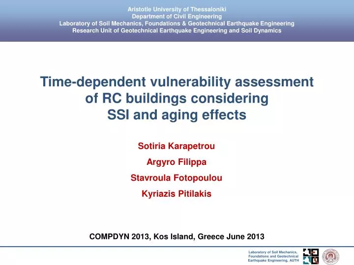
Aristotle University of Thessaloniki Department of Civil Engineering Laboratory of Soil Mechanics, Foundations & Geotechnical Earthquake Engineering Research Unit of Geotechnical Earthquake Engineering and Soil Dynamics. Time-dependent vulnerability assessment of RC buildings considering

E N D
Aristotle University of Thessaloniki Department of Civil Engineering Laboratory of Soil Mechanics, Foundations & Geotechnical Earthquake Engineering Research Unit of Geotechnical Earthquake Engineering and Soil Dynamics Time-dependent vulnerability assessment of RC buildings considering SSI and aging effects SotiriaKarapetrou ArgyroFilippa StavroulaFotopoulou KyriazisPitilakis COMPDYN 2013, Kos Island, Greece June 2013
Structural models Low-rise structural model • 2-storey, 1-bay RC MRF building • Designed based on Greek modern seismic code • Material properties: ConcreteC20/25 • SteelB500C • Fundamental period: T1=0.3936sec Gelagoti (2010)
Structural models • Mid-rise structural model • 4-storey, 3-bay RC MRF building • Designed based on • modern seismic code of Portugal • Material properties: Concretefc=28MPa • Steelfy=460MPa • Fundamental period: T2=0.5018sec Abo El Ezz (2008)
Numerical modeling • Finite element code OpenSees • Material inelasticity • Distributed material plasticity(fiber based approach) Unconfined concrete: Kent and Park model (1971) Confined concrete: Modified KentandParkmodel (Scottetal 1982) Steel: uniaxial bilinear steel material object with kinematic hardening
Soil-structure interaction (SSI) modeling SSI two-step analysis (Fotopoulou et al. 2012) • 1ststep: 1Dequivalent linear analysis of the soil column • 2ndstep: Impedance function by Mylonakis et al. (2006) • Vs,30=300m/sec CyberQuake G-γ-D byDarendeli(2001) → free field surface motion → effective shear strain of the surface layer γeff
Soil-structure interaction (SSI) modeling SSI two-step analysis (Fotopoulou et al. 2012) • 1ststep: 1Dequivalent linear analysis of the soil column • 2ndstep: Impedance function by Mylonakis et al. (2006)
Soil-structure interaction (SSI) modeling SSI one-step analysis • OpenSees • Calibration of the soil parameters in terms of G = f(γ) και D(%) = f(γ)based on1D equivalent linear analysis conducted in Cyberquake for the SSI two-step analysis • Soil profile 120m x 30m, 3600 four node quadrilateral elements • Soil quad element 1m x 1m Rigid beam-column element Free field Common nodes-Apropriate constraints 30.0m Elastic soil layers Vs,30=300m/sec 30.0m Input Motion Elastic Bedrock Vs=1000m/sec 120.0m Lysmer-Kuhlemeyer (1969) dashpot
Soil-structure interaction (SSI) modeling SSI one-step analysis • Soil profile 120m x 30m, 3600 four node quadrilateral elements • Soil quad element 1m x 1m • Lysmer-Kuhlemeyer dashpot at the base • Elastic soil layers 30.0m • Elastic bedrock Vs=1000m/sec • Calibration of the soil parameters in terms of G = f(γ) και D(%) = f(γ)based on1D equivalent linear analysis conducted in Cyberquake for the SSI two-step analysis • Soil – structure: common nodes, appropriate constraints
Corrosion modeling Corrosion scenario for the t=50 years • Main parameters: W/C, Ccrit, Tini, icorr, Di, n • Probabilistic modeling of corrosion initiation time due to chloride ingress according to FIB-CEB Task Group5.6 (2006) • Time-dependent loss of cross sectional area of reinforced bars based on Gosh και Padgett (2010) Distribution of Chloride corrosion initiation time Tini mean = 2.96 years Standard Deviation = 2.16 years
Nonlinear Dynamic Analysis • 2D nonlinear time-history analysis for t=0 and 50 years • 8 outcropping records corresponding to sites classified as rock or stiff soil according to EC8 • 3 scaling levels in terms of PGA: 0.1g 0.3g 0.5g
Definition of Damage States • Ghobarah (2004): max ISD(%) for ductile and non-ductile MRF systems • Scenariot=0 years: damage states for MRF – ductile structures • Scenariot=50 years: damage states for MRF – non-ductile structures
Definition of Damage States • Ghobarah (2004): max ISD(%) for ductile and non-ductile MRF systems • Scenariot=0 years: damage states for MRF – ductile structures • Scenariot=50 years: damage states for MRF – non-ductile structures
Time-dependent fragility curves Lognormal distribution t : reference time m(t), β(t): PGA median values and logarithmic standard deviations at different points in time t along the service life (t=0 and 50 years)
Time-dependent fragility curves Uncertainties • βD: demand (variability in the numerical results) • βC: capacity (HAZUS) • βds: definition of damage state (HAZUS)
Fragility curves • PGA-ISDmax (%) for the low rise structures considering fixed and compliant condition for t=0 and 50 years
Fragility curves Comparison with literature Low rise strucural model designed based on modern seismic codes (t=0 έτη)
Fragility curves Comparison with literature Mid rise strucural model designed based on modern seismic codes (t=0 έτη)
Fragility curves • Low rise structural model Aging effects→Increase in vulnerability
Fragility curves • Mid rise structural model Aging effects→Increase in vulnerability
Fragility curves • Fixed and compliant (Vs=300m/sec) foundation conditions for t=0years SSI and foundation compliance →Increase in vulnerability
Fragility curves • Fixed and compliant (Vs=300m/sec) foundation conditions for t=0years SSI →Decrease in vulnerability
Fragility curves • Substructure (two-step) and direct (one-step) methods for SSI modeling
Fragility curves • Percentage increase in vulnerability due to soil compliance
Fragility curves • Percentage decrease in vulnerability due soil-structure interaction
Conclusions • aging effects : • affect the dynamic response and the seismic vulnerability of the structures • corrosion of reinforcement : • is considered as a loss of cross sectional area of reinforced bars • leads to significant increase of structure vulnerability due to the considered “worst case scenario” • soil deformability and soil compliance: • modify the structural response of the analyzed structures resulting to higher vulnerability values. • depends on: the characteristics of the building, the input motion and the soil properties.
Conclusions • soil-foundation-structure interaction (SFSI): • leads to decrease in structural vulnerability • the uncoupled two-step approach (substructure method) leads to higher vulnerability (overestimation due to uncertainties related, among others, to the evaluation of the impedance function) • further research in: • definition of limit states for corroded structures based on adequate analytical, experimental and empirical data • incorporation of the fully probabilistic models within the dynamic analysis