Download
1 / 37
370 likes | 488 Views
Low-Emittance Tuning Techniques at C ESR TA. October 3, 2011 Jim Shanks for the C ESR TA Collaboration. Overview. CesrTA & C apabilities Emittance correction procedure Survey and alignment BPM calibration methods Emittance correction Results from recent CesrTA runs.

E N D
Low-Emittance TuningTechniques at CESRTA October 3, 2011 Jim Shanksfor the CESRTA Collaboration
Overview CesrTA & Capabilities Emittance correction procedure Survey and alignment BPM calibration methods Emittance correction Results from recent CesrTA runs LER11 – Low-Emittance Tuning at CesrTA
CesrTA - Parameters wigglers Dispersion x y z(m) *Wigglers account for 90% of synchrotron radiation at 2.1GeV LER11 – Low-Emittance Tuning at CesrTA
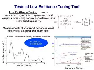
Capabilities: Resonant Measurements BPM system: Capable of multibunch, turn-by-turn readout Measure positions by peak detection for an arbitrary bunch pattern (down to 4ns bunch spacing) on every turn Collect up to ~250k turns of beam position data Turns depth is buffer-limited; dependent on number of bunches recorded Most of the analysis used in emittance correction is derived from TBT data Beta functions, betatron phase, coupling, dispersion Advantages: fast, minimally-invasive, no hysteresis Typical resonant excitation data acquisition outline: Initial setup: lock tune trackers: ~1 minute Record TBT data: ~30s 40,000 turns used for most common measurements Analyze data to extract betatron phase + coupling, or dispersion: ~10s LER11 – Low-Emittance Tuning at CesrTA
Betatron Phase and Coupling At each BPM button, measure the signal intensity on a sequence of turns • Typically N = 40k turns of data are recorded • Horizontal and vertical measurements are done simultaneously • Initially, tunes must not be near resonances, to prevent cross-talk between h/v modes BPM modules compute FFT amplitude of horizontal motion (Similar equations for vertical mode) at button j is a sum over turns i: (in-phase) (out-of-phase) qt,h(i) = phase of tune tracker drive signal (phase-locked to horiz. tune) on turn i aj(i) = signal on turn i at button j Define: = x/y components, via standard BPM “D/S” = Total FFT amplitude of x/y signal at the horiz/vert mode Phys. Rev. ST Accel. Beams3, September 2000, 092801 LER11 – Low-Emittance Tuning at CesrTA
Coupling: Definition Reminder– Cornell uses Cbar to describe coupling for 4x4 transport: Cbar = C matrix in normalized coordinates LER11 – Low-Emittance Tuning at CesrTA
Betatron Phase and Coupling Betatron phase and couplings (Cbar) are defined by: from horiz. mode from vert. mode from horiz.mode from vert.mode Cbar12 is “out-of-phase” component of coupling matrix • Independent of physical BPM tilts Cbar 22 and Cbar11 are “in-phase” components • Dependent on BPM tilts Similarly, when resonantly exciting beam longitudinally and measuring beam position at thesynch tune, one obtains the dispersion (“AC dispersion” technique) LER11 – Low-Emittance Tuning at CesrTA
Further Capabilities Skew quad trims on sextupoles Rewired several unused vertical steering trims on sextupoles near arc wiggler straights to generate skew-quad-like fields Expands the total number of skew quadrupoles from 15 to 27 Allows for dispersion correction through arc wigglers Conversely, also able to intentionally generate vertical emittance by coupling horizontal dispersion into the vertical mode in arc wigglers X-ray Beam Size Monitor (xBSM) 1D vertical diode array Capable of measuring TBT bunch size for ≥4ns-spaced bunches Primary tool for measuring success of vertical emittance corrections LER11 – Low-Emittance Tuning at CesrTA
X-ray Beam Size Monitor X-ray Beam Size Monitor (xBSM) Images X-rays from bending magnet Uses 1D 32-chan vertical diode array Has 3 choices for Optics Element Adjustable Slit (“Pinhole” optics) Fresnel Zone Plate (FZP) Coded Aperture (CA) FZP • Functions • Capable of measuring TBT bunch size for ≥ 4ns-spaced bunches • 40 dB gain adjustment • Primary tool for checking vertical emittance corrections CA LER11 – Low-Emittance Tuning at CesrTA
Emittance Correction Procedure • Long-term (~few times a year): • Survey and alignment • Medium-term (at start of CesrTA runs): • Calibrate BPM button-to-button gains • Calibrate BPM tilts • Calibrate BPM / quad center offsets • Short-term (daily or more, during CesrTA runs): • Re-time BPMs (before every measurement) • Measure and correct orbit • Measure and correct betatron phase and coupling • Measure: orbit, betatron phase/coupling, and dispersion; correct simultaneously LER11 – Low-Emittance Tuning at CesrTA
Emittance Correction Procedure • Long-term (~few times a year): • Survey and alignment • Medium-term (at start of CesrTA runs): • Calibrate BPM button-to-button gains • Calibrate BPM tilts • Calibrate BPM / quad center offsets • Short-term (daily or more, during CesrTA runs): • Re-time BPMs (before every measurement) • Measure and correct orbit • Measure and correct betatron phase and coupling • Measure: orbit, betatron phase/coupling, and dispersion; correct simultaneously LER11 – Low-Emittance Tuning at CesrTA
Survey and Alignment Dipole Rolls Quad Tilts Quad Vertical Offsets s = 193 mm s = 227 mrad s = 206 mrad 2008 s = 27 mm s = 130 mrad s = 50 mrad 2011 LER11 – Low-Emittance Tuning at CesrTA
Emittance Correction Procedure • Long-term (~few times a year): • Survey and alignment • Medium-term (at start of CesrTA runs): • Calibrate BPM button-to-button gains • Calibrate BPM tilts • Calibrate BPM / quad center offsets • Short-term (daily or more, during CesrTA runs): • Re-time BPMs (before every measurement) • Measure and correct orbit • Measure and correct betatron phase and coupling • Measure: orbit, betatron phase/coupling, and dispersion; correct simultaneously LER11 – Low-Emittance Tuning at CesrTA
BPM Gain Calibrations Recalibrate BPM gains at the start of CesrTA runs Method: Resonantly excite beam in horizontal and vertical Collect TBT data for 1024 turns at all BPMs Gain map analysis of TBT data assumes a second-order expansion of small-orbit response of buttons– Phys. Rev. ST Accel. Beams13, September 2010, 092802 Time required: 30 seconds to acquire data, < 5 minutes to analyze and load sgains = 4.2% Standard deviations from the mean of seven consecutive data sets Distribution of Fitted Gains for one data set LER11 – Low-Emittance Tuning at CesrTA
BPM Tilt Calibrations Dispersion and BPM tilts: A 10mrad BPM tilt couples a 1m horizontal dispersion to an apparent (non-physical) 1cm vertical dispersion Limits the effectiveness of vertical dispersion correction at that BPM Simulations suggest 1cm RMS vertical dispersion will generate a residual vertical emittance of ~10pm Tilt calibration procedure: Measure coupling (Cbar12) and correct using all skew quadrupoles Recall: Cbar12 is insensitive to BPM tilts, as it is out-of-phase coupling Remeasure phase/coupling Fit residual Cbar12 with model, using skew quadrupoles The residuals of (measured – model) Cbar 22, 11 are related to BPM tilts LER11 – Low-Emittance Tuning at CesrTA
BPM Tilt Calibrations Fit residual Cbar22, Cbar 11 (in-phase betatron coupling) using BPM tilts Average fitted tilts plotted from 58 coupling measurements In the process of understanding these fits Standard Deviations of 58 fitted tilts at each BPM RMS BPM tilt: 22mrad LER11 – Low-Emittance Tuning at CesrTA
BPM/Quad Offset Calibrations Vertical offsets between quadrupole and BPM centers will introduce vertical kicks, therefore vertical dispersion and vertical emittance Calibrate vertical BPM/quad offsets in the following way: Measure betatron phase twice, changing one quadrupole’s strength in-between Determine Twiss parameters (b, phase f, and tunes n) and closed orbits from each of the two TBT data sets Fit the difference of closed orbit measurements with a kick dy’ at the quadrupole Fit the difference of betatron phase measurements with a kick dk at the quadrupole Quadrupole offset is then yoffset = (1/Lquad) (dy’/dk) + y0(y0 = nominal closed orbit) Iterate until convergence Quadrupole / BPM centers then known to < 300 microns Takes about 2 hours to center all 100 quadrupoles LER11 – Low-Emittance Tuning at CesrTA
Emittance Correction Procedure • Long-term (~few times a year): • Survey and alignment • Medium-term (at start of CesrTA runs): • Calibrate BPM button-to-button gains • Calibrate BPM tilts • Calibrate BPM / quad center offsets • Short-term (daily or more, during CesrTA runs): • Re-time BPMs (before every measurement) • Measure and correct orbit • Measure and correct betatron phase and coupling • Measure: orbit, betatron phase/coupling, and dispersion; correct simultaneously LER11 – Low-Emittance Tuning at CesrTA
Emittance Correction I Phase after correction: Horizontal vertical Coupling after correction: • Time in individual BPM buttons • Timing drifts by ~10’s of picoseconds over the course of an hour • Re-time before every measurement • minimal timing step is 10ps • DSignal |peak( t0 ±10ps ) ~ 5x10⁻⁴ • One iteration takes about one minute • Measure closed orbit and correct with all horizontal and vertical steerings • Takes about 30 seconds to measure, analyze, load corrections, and re-measure orbit • Measure betatron amplitudes, phase advance and transverse coupling • Use all 100 quadrupoles and 27 skew quads to fit the machine model to the measurement, and load correction • Typical correction levels: • Df (meas-design) < 2° 3% beta beat • Cbar12 < 0.005 • One iteration takes about one minute LER11 – Low-Emittance Tuning at CesrTA
Emittance Correction II Vertical beam size after correction using xBSM pinhole optic sy = 15 mm by = 40m Vertical dispersion after correction hy 4. Re-measure closed orbit, phase and coupling, and dispersion • Simultaneously minimize a weighted sum of orbit, vertical dispersion, and coupling using vertical steerings and skew quads • Typical level of correction: measure hy ~15mm • Measure ey < 10pm with xBSM • At 0.5mA = 0.8x10¹⁰ positrons • Suggests hy measurement is resolution-limited • Turnaround time: ~5 minutes per correction iteration: • Correct orbit • Correct phase/coupling • Correct orbit + coupling + dispersion LER11 – Low-Emittance Tuning at CesrTA
Further Improvements: In Progress During June 2011 run, we began work on further improvements to LET setup: Conditions have been recovered at two new energies: 1.8GeV and 2.3GeV, in addition to standard 2.085GeV First tests of simultaneous beam size measurements in horizontal, vertical, and longitudinal Horizontal interferometer setup; multi-turn integration Longitudinal via streak camera Vertical using xBSM xBSM data acquisition can now be automated Acquires a 4096-turn snapshot every ~5 seconds, processing the first 100 turns on the fly A more continuous data acquisition scheme is under development New digital tune tracker Capable of phase-locking to any single bunch in the ring LER11 – Low-Emittance Tuning at CesrTA
vBSM + Streak Camera Setup L3 setup includes beam splitter to allow simultaneous horizontal and longitudinal beam size measurements LER11 – Low-Emittance Tuning at CesrTA
Initial IBS Studies April 2011, 2.085GeV, single bunch of positrons, fill to ~6.5mA (~1x10¹¹ e+) Use xBSM to record 100 consecutive turns of vertical beam size at several currents Vertical Bunch Size vs. Current from xBSM, pinhole optic • Overlay on plot: simple IBS model, with the following inputs: • Ideal lattice (no misalignments) • Zero-current ey assumed to be 3-4pm • Parameter r is a “fudge factor” to allow comparison between ideal simulation and real-world machine • r ~ (ey from coupling) / (ey from hy) • Further analysis is necessary LER11 – Low-Emittance Tuning at CesrTA
H+L IBS Measurements Note: precision calibrations have not been done on these instruments! We intend to do more IBS studies in the upcoming December 2011 run • First tests of simultaneous horizontal and longitudinal beam size measurements in June 2011 Longitudinal Beamsize vs. Current from streak camera Horizontal Beamsize vs. Current from interferometer LER11 – Low-Emittance Tuning at CesrTA
Touschek Lifetime • Touschek lifetime data acquired at three energies: • 1.8GeV, 2.085GeV, 2.3GeV • We are in early stages of understanding the results LER11 – Low-Emittance Tuning at CesrTA
Summary Survey and alignment has made significant progress We are in the process of understanding BPM tilt calibrations Demonstrated efficacy of optics corrections using resonant excitation data Typical vertical emittance after correction is ey < 10pm Initial “proof-of-concept” IBS and Touschek measurements have been made Further analysis is necessary Will be studied further in December 2011 CesrTA run, with more tests of simultaneous horizontal, vertical, and longitudinal bunch size We encourage interested collaborators to participate! LER11 – Low-Emittance Tuning at CesrTA
Backup Slides LER11 – Low-Emittance Tuning at CesrTA
Horizontal vBSM Horizontal beam size measured with visual-spectrum interferometer (l = 500nm) LER11 – Low-Emittance Tuning at CesrTA
Characterization of BPM Gain Errors Signal at each button depends on bunch current (k) and position (x,y) Signals on the four buttons are related by symmetry Combining sums and differences we find the following relationship, good to second order LER11 – Low-Emittance Tuning at CesrTA
Gain characterization simulation Using a map that reproduces the “exact” dependence of the button signals on the bunch positions we generate B1,B2,B3,B4 for each of 45 points on a 9mm x 5mm grid In first order c=0, and therefore B(+--+) = 0. Evidently the first order approximation is not very good enough this range. The small deviations from the straight line at large amplitudes is a measure of the higher than second order contributions. LER11 – Low-Emittance Tuning at CesrTA
Gain characterization simulation Introduce gain errors Zero offset, nonlinearity, and multi - valued relationship i n is a measure of gain errors. LER11 – Low-Emittance Tuning at CesrTA
Minimize with respect to gj to determine gains Fit typically reduces 2 by two orders of magnitude LER11 – Low-Emittance Tuning at CesrTA
Low emittance tuning - modeling • Introduce misalignments • BPM parameters LER11 – Low-Emittance Tuning at CesrTA
Emittance Tuning Simulation - Create 1000 models - Apply tuning procedure Emittance distribution after each step LER11 – Low-Emittance Tuning at CesrTA
LET Correction Simulations Software has been developed to simulate resonant excitation data, including: Magnet misalignments and errors BPM transverse misalignments, resolution, gain errors, tilts, timing errors, etc. Tune trackers to drive beam Resonantly excite the beam, damp until equilibrium, then record turn-by-turn positions (with BPM errors applied) Process data as our control software does, emulating: BPM gain maps BPM tilt calibrations Iterative LET correction procedure based successive measurements See Excel spreadsheet for example results LER11 – Low-Emittance Tuning at CesrTA
Low Emittance Tuning • The same simulation predicts 95% seeds are tuned to <2pm if BPM • - Offsets < 100μm • - Button to button gain variation < 1% • - Differential resolution < 4 μm (1 μm for ATF lattice) • - BPM tilt < 10mrad • We have beam based techniques for calibrating gain variation based on turn by turn position data • Determining tilt from coupling measurements • We are exploring a tuning scheme that depends on measurements of the normal modes of the dispersion rather than the horizontal and vertical and that is inherently insensitive to BPM button gain variations and BPM tilts. LER11 – Low-Emittance Tuning at CesrTA
Hints of FII signal in bunch-by-bunch data Ion Frequency • Calculated ion frequency between 5 and 10 Mhz. 1.8 GeV • Analysis is FFT of 45 bunches at 1 BPM averaged over 4096 turns • Data needs to be understood in context of trapping condition. LER11 – Low-Emittance Tuning at CesrTA