Download
1 / 1
10 likes | 140 Views
CM. LAM. Force (N). Time (min). Laser Assisted Machining P. Mitchell, Prof. G. Byrne and R. Byrne Email: paul.mitchell@ucd.ie Abstract

E N D
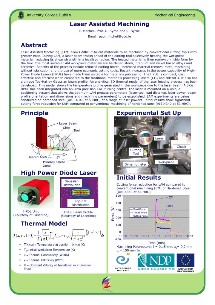
CM LAM Force (N) Time (min) Laser Assisted Machining P. Mitchell, Prof. G. Byrne and R. Byrne Email: paul.mitchell@ucd.ie Abstract Laser Assisted Machining (LAM) allows difficult-to-cut materials to be machined by conventional cutting tools with greater ease. During LAM, a laser beam tracks ahead of the cutting tool selectively heating the workpiece material, reducing its shear strength in a localised region. The heated material is then removed in chip form by the tool. The most suitable LAM workpiece materials are hardened steels, titanium and nickel based alloys and ceramics. Benefits of the process include reduced cutting forces, increased material removal rates, machining without lubrication and the use of more economic cutting tools. Recent increases in the power capability of High-Power Diode Lasers (HPDL) have made them suitable for materials processing. The HPDL is compact, cost effective and efficient when compared to the traditional materials processing lasers (CO2 and Nd:YAG). It also has a unique Top-Hat by Gaussian beam profile. An analytical 3D thermal model of the laser heating process has been developed. This model shows the temperature profile generated in the workpiece due to the laser beam. A 3kW HPDL has been integrated into an ultra precision CNC turning centre. The laser is mounted on a unique positioning system that allows the optimum LAM process parameters (laser-tool lead distance, laser power, beam profile orientation and dimensions and machining parameters) to be established. LAM experiments are being conducted on hardened steel (AISI 4340 at 53HRC) at a range of laser powers. Initial results show significant cutting force reduction for LAM compared to conventional machining of hardened steel (AISI4340 at 53 HRC). Experimental Set Up Principle Laser Beam Chip Tool Laser Chuck Cutting Tool Vc Heated Area Primary Shear Zone Workpiece Dynamometer High Power Diode Laser Initial Results Cutting force reduction for LAM compared to conventional machining (CM) of Hardened Steel (AISI4340 at 53 HRC) Gaussian Distribution Top-hat Distribution HPDL Unit (Courtesy of Laserline) HPDL Beam Profile (Courtesy of Laserline) Thermal Model • T(x,y,z) = Temperature at position (x,y,z) (K) • T0= Initial Workpiece Temperature (K) • = Thermal Conductivity (W/mK) • = Thermal Diffusivity (W/m2) • U = Constant Velocity of Translation in X Direction (m/s) Machining Parameters: f = 0.15mm, ap= 0.2mm vc= 150 m/min