Download
1 / 17
170 likes | 261 Views
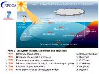
Mudstone CO 2 sealing efficiency. K. Kurtev, A. Aplin and S. Abrakasa University of Newcastle. Evidences for leakages in North Sea. High TOC due to asphaltenes. Tmax is low – no HC formation. Modelling studies Goals

E N D
Mudstone CO2 sealing efficiency K. Kurtev, A. Aplin and S. Abrakasa University of Newcastle
High TOC due to asphaltenes Tmax is low – no HC formation
Modelling studies Goals 1. To identify the key structural control factors in mudstones important for CO2migration; 2. To recognize and formulate the basic typesof heterogenity of those key flow control factors ( main mudstone texture types resulted from the different regimes of sedimentation & consolidation); 3. To define method(s) for parametrization of the the basic types of textural / structural connectivity responsible for CO2 leakage;
CO2 Leaking Systems Leakage is a multiscale Flow Process in Clay-Rich Sediments Intermediate scale: log interval or ~ 1 m scale Sample scale Seismic scale • Leaking Elements: • Pore network; • - Grain Sizes; • - Microfractures; • Leaking Elements: • Thin beds connectivity; • Fracture Connectivity; • Leaking Elements: • Fault (zone) permeability; • Seal integrity;
Facies A Facies C Facies B FaciesD Basic facies defined at Wales outcrops Each faciess is characterised by a specific internal architecture (i.e. internal geometry) indicated as its texture. Defined are: Four dominant texture types: A - high clay content mud flow; B - debris flow deposits; C - thin bedded sequence; D – thin, more laterally continuous and persistent debris flow deposits;
Modelling steps: • Define Clay content from image: • a) by linear “projection” of the gray colour scale to clay • content range ; • b) by recognition of the lighter colours as degree of coarse • silt content and then calculation of the clay% based on an • established correlation; • Porosity calculation based on Clay% and user-defined • Effective Stress (Yang and Aplin1998); • Vertical and Horizontal permeability calculated from porosity • based on correlations obtained by Yang and Aplin (1998); • We Always should mind the artefacts imposed from the image quality. • Needed is a calibration vs. real experiments
Expected result Flow Modelling results (equivalent permeability) Texture Modelling ~ 1 m scale NZ1 Intermediate texture NZ2 (Stochastic Simulation)
Model ZZ1 Parameters , σeff = 7 MPa Porisity % Picture Clay % Kh [nD] Kv [nD]
Upscaled Kh and Kv for twomodels at different Effectife Stress ( 7, 15 , 23 , 45 MPa) NZ1 NZ2
Conclusions • Permeable thin bed connectivity is an important • factor for the mudstone sealing efficiency; • Upscaled flow properties highly depends on mudstone • texture – defined heterogenity; • - Previous experience on HC leakage could be used • as a basis for evaluation of the mudstone CO2 sealing • efficiency;