Download
1 / 20
200 likes | 358 Views
ME414 Spring 2006 Design Project 2 Heat Exchanger. Ugo Anyoarah Osinanna Okonkwo Vinay Prisad Daniel Reed. Introduction. Introduction Project Definition Design Optimization Goals First Design Pass Second Design Pass Other Factors Design Results. Project Definition.

E N D
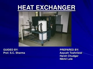
ME414Spring 2006Design Project 2Heat Exchanger Ugo Anyoarah Osinanna Okonkwo Vinay Prisad Daniel Reed
Introduction • Introduction • Project Definition • Design Optimization Goals • First Design Pass • Second Design Pass • Other Factors • Design Results
Project Definition • During the make of a liquid chemical product, its temperature needs to be reduced by 10 degrees Celsius. • Mass flow rate is 80,000 kg/hr • Fluid enters the heat exchanger at 35 C and should leave at 25 C • Material properties of this chemical product can be approximated as water • Cooling of the chemical product will be achieved by using treated city water • City water is available at 20 C • Mass flow rate is adjustable and one of the design parameters to be selected • Exit temperature of city water from the heat exchanger is a function of the selected mass flow rate
Design Optimization Goals • Must cool the chemical from 35 C to 25 C • Heat exchanger length can not exceed 7 m • Heat exchanger shell diameter can not exceed 2 m • Minimize heat exchanger shell and tube weight hence the cost • Minimize heat exchanger pressure drop
First Design Pass • Matlab Variables • 4 variables • Tube_OD (6.350 – 25.4)e-3 meters • Shell_ID (.8 – 2) meters • Tube_Len (4 – 7) meters • N_tube (40 – 100) • 7 levels • Gives 7^4 = 2401 runs
First Design Pass • Matlab Variables • Tube and Shell Material set to Aluminum • Consistent expansion between shell & tubes. • Maximum heat transfer • Corrosion Resistance (chemical similar to H20) • Tube pass set to two (2) • Most space efficient • Baffle Space set to 0.1048 m • Baffle Cut set to 0.3750 m • City water flow rate set to 38.8889 Kg/Sec
First Design Pass • Matlab Results • Weight: 2069.17 – 22415.9 • DP Shell: 335149 – 6364756 • DP Tube: 17701.66 – 4.26e11 • Q Calc: 107043.7 – 919867.5 • 2401 runs = AAARRRGGGHHH!!!!!
First Design Pass • Findings • MiniTab will not do Pareto charts for systems with more than 2 levels. • Higher levels ( >4) are beneficial for identifying linear regions and critical areas.
Second Design Pass • Used Excel to find variable combinations with Qcalc/Qdes = 1 +/-10% • 12 combinations met criteria • Used the max and min in 2nd iteration of Matlab (2 level)
Second Design Pass • Matlab Variables • 4 variables • Tube_OD (9.535 – 25.4)e-3 meters • Shell_ID (.8 – 1) meters • Tube_Len (6.5 – 7) meters • N_tube (90 – 100) • 2 levels • Gives 2^4 = 16 runs
Second Design Pass • Matlab Results • Weight: 3444 – 5773 • DP Shell: 122279 – 3933472 • DP Tube: 24799 – 41293392 • Q Calc: 844667 – 919867 • 16 runs = MMM! (Much more manageable)
Second Design Pass • Check W/ Matlab • Number of Tubes N = 100.00 • Number of Passes = 2.00 • Tubes OD OD = 0.0191 m • Tubes ID ID = 0.0135 m • Tube Length L = 6.7500 m • Tube Pitch PT = 0.0238 m • Shell ID = 0.9000 m • Baffle Space = 0.1048 m • Number of Baffles = 63.0000 m • Desired Heat Transfer Rate = 928501.84 W • Calculated Heat Transfer Rate = 843364.57 W • Difference = 85137.28 W • Desired-to-Calculated Ratio = 1.10 • Shell Side Delta-P = 1517783.93 Pa • Tube Side Delta-P = 138509.45 Pa • Total HE Weight = 4550.87 kg
Second Design Pass • Fouling Factor • Increased tube number to account for fouling • 116 tubes required for Q/q=1 • 135 tubes for Q/q=0.91 • DP Shell: Unchanged • DP Tube: 79943.83 Pa • Weight: 4607.82 Kg
Other Factors • Full Factorial desirable • City Water Flow Rate • Baffle Spacing • Baffle Cut Height • Tube Pitch • Tube Layout Angle • Yields 12 factors • Even 2 levels is long: 4096 data points
Design Results • Length: 6.5m • Shell ID: 1m • Tube OD: 19.1mm • Tube Length: 6.75m • Number of Tubes: 135