Download
1 / 35
350 likes | 436 Views
OHIO UNIVERSITY Avionics Engineering Center School of Electrical Engineering & Computer Science. Alternate Communications Spectrum Study (ACSS) for Aviation Data Links (ADL) March 2004. David W. Matolak, Ph.D. Assistant Professor 322E Stocker Center Ohio University Athens, OH 45701

E N D
OHIO UNIVERSITY Avionics Engineering Center School of Electrical Engineering & Computer Science Alternate Communications Spectrum Study (ACSS)for Aviation Data Links (ADL)March 2004 David W. Matolak, Ph.D. Assistant Professor 322E Stocker Center Ohio University Athens, OH 45701 phone: 740-593-1241 fax: 740-593-0007 email: matolak@ohiou.edu
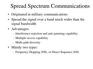
Outline • Overall Study Aim: • Identify key factors involved in the use of alternate spectrum in various bands for a future integrated CNS data link • Task list • Current related effort overview • Desired ADL attributes • Potential spectral regions • System design approach steps • Summary Ohio University
Motivation • Need for additional communication capabilities in civilian aviation is well documented • FAA’s National Airspace System (NAS) “modernization blueprint” [1] • Numerous papers from recent professional conferences in the field, such as • Digital Avionics Systems Conferences (DASC), e.g., [2], [3] • Integrated Communications, Navigation, and Surveillance (ICNS) workshops, e.g., [4], [5] • Growth of passenger communications is also expected [6] • We thus begin with the premise that new capabilities are unquestionably in need, for the benefit of the aviation community. Ohio University
Task List }FOCUS • Tasks 1. Spectrum Availability 2. System Coexistence 3. Existing Hardware Review 4. Waveform Studies 5. Multiple Access 6. Satellites, Navigation, etc. • Focus on the two or three lowest layers of the communications protocol stack: • physical layer (PHY) • data link layer (DLL) • medium access control (MAC) layer }FUTURE Ohio University (…still LOTS to do!)
Current Related Efforts • NEXCOM is (quote) • “FAA’s radio system of the 21st century … • An analog/digital system incorporating latest technological advances in radio communications • Will provide capability to • accommodate additional sectors and services • reduce logistical costs • replace expensive to maintain VHF and UHF radios • provide data link communications capability • reduce A/G RF Interference • provide security mechanisms • When completed over 46,000 radios will be installed throughout the FAA system.” Ohio University
Current Related Efforts (2) • NEXCOM • Operates in dedicated aero spectrum at VHF • Uses existing FDMA channel structure • Modes 1-3, plus analog 8.33 kHz AM • For mode 3 (TDMA) • Maximum data rate is 19.2 kbps for ALL 4 time slots • Differential 8PSK modulation • 3 or 4 time slots • Time division duplexing • Point-to-point AG and GA, plus GA broadcast Ohio University
Current Related Efforts (3) • Small Aircraft Transportation System (SATS) (quote) • “… project's initial focus to prove that four new operating capabilities will enable safe and affordable access to virtually any runway in the nation in most weather conditions.” [12] • on-board computing, • advanced flight controls, • Highway in the Sky displays, • automated air traffic separation and sequencing technologies.” • Last one relies on efficient and secure CNS Ohio University
Current Related Efforts (4) • Small Aircraft Transportation System (SATS) • Recent demo done (NASA Glenn) using VDL4 • Next stage planned for this capability is transfer of demo system to a SATSLab and the Airborne Internet Consortium for experimental evaluations and commercialization. • May require substantial changes to demo system in terms of components, capabilities, and modes of operation. • That is, final SATS AI communication system (even lowest few layers) will likely be substantially different from demo system, in areas of • frequency band of operation • available data rates and channel bandwidths • number of simultaneous users • range and spatial discrimination Ohio University
Current Related Efforts (5) • Universal Access Transceiver (UAT) • Mostly applied to surveillance applications, in particular Automatic Dependent Surveillance—Broadcast (ADS-B). • In this application, successfully deployed on a trial basis in Alaska. Plans for its use in contiguous US may be underway. • Fairly simple (hence robust) binary modulation, to enable reduction of aircraft radio costs. • Like NEXCOM’s VDL3, it uses time slotting, and burst transmissions • Aircraft transmissions not assigned to slots--randomly accessed [14] • Current UAT transceivers canNOT provide individual message addressing and true peer-to-peer connectivity Ohio University
Current Related Efforts (6) • Universal Access Transceiver (UAT) • Requires a dedicated 1 MHz channel • Time division duplexing • Maximum data rate is 1004.167 kbps for ALL users (Total) with no packet collisions and no overhead • Practical throughput ~ 0.36(0.82)1Mbps 295 kbps for all users (Total) • Point-to-point AG and GA, plus GA broadcast Ohio University
Current Related Efforts (7) • Airborne Internet Consortium • Recently formed group (2003?) [9], also termed the Airborne Internet Collaboration Forum • Members from aviation industry, government organizations, academia • Group purpose • Encourage the development of an open systems architecture and standards for aviation digital communications • Foster and promote internet protocols in aviation • Develop intellectual content to guide and influence public and private investment Ohio University
Current Related Efforts (8) • Airborne Internet Consortium • Group meetings have sought participation, discussed group’s aims, and outlined items for a workplan • The nascent workplan items of direct relevance to our work are the following: • Integrated CNS requirements • Architectural candidates, trade-offs and evaluation * • AI system design • Test and evaluation • AI design and use of VDL, SAT, 802.11… * • Applicable technology assessment * • Applicable communication standards assessments. * Ohio University
Desired ADL Attributes • For widespread acceptance, ADL system must offer capabilities not present or not fully supported by existing systems. • Generally New ADL system • Should offer higher Rb than existing systems • Should be able to serve large # users “simultaneously” in any given geographic area • Geographic area (range for air-ground, ground-air, or air-air communications) should be as large as possible • Connectivity should be ideally peer-to-peer Ohio University
Desired ADL Attributes (2) • Allow wide variety of data rates & data traffic types, with differing requirements on QoS • message latency (delay) • integrity • variety of message rates would enable ADL system use for multiple purposes, which would enhance acceptance. • Last, system should be reliable, which redundancy, and it should be secure in several ways • Difficult to spoof (allow unauthorized entity to masquerade as a system user or operator, thereby disrupting service) • Difficult to eavesdrop upon, for privacy reasons • Difficult to disrupt or overload Ohio University
Desired ADL Attributes (3) • All these attributes are QUALITATIVE • You can not build any complex system with qualitative requirements! • Can evaluate all existing efforts in terms of these attributes, at least relative to one another, and consider • Technology: many meanings, but, existing or not (yet)? • Spectrum Availability: aero or not? • Waveforms: what features are most important? • Propagation: can we reach as far as we need to? • Alternative systems: WLANs, cellular, 802.20… • Finally: standardization essential Ohio University
narrowband DS-SS “despread” Power Spectral Density frequency Note on Spread Spectrum • Use of spread spectrum noted for security advantages • Spread spectrum also of interest for • Robustness (to multipath, interference…) • Popularity • All new cellular systems are spread spectrum • Wireless LANs are spread spectrum • All secure military systems use spread spectrum • EUROCONTROL experimenting with spread spectrum • This has focused some of our work on analysis & simulation of performance of SS Ohio University
Potential Spectral Regions • In principle there exist vast amounts of unused spectrum, at frequencies above those in common use (e.g., V band ~ 45 GHz) • Technologies are not presently available to economically deploy communication systems in these bands • Propagation conditions favor use of lower frequencies for transmission ranges of interest in the aeronautical case (tens of meters to a few hundred kilometers) • Hence adequate to restrict attention to frequency bands below Ku band (12 GHz), at least for AG and GA communication (higher f’s possible for satellites) Ohio University
Potential Spectral Regions (2) • For the lower frequency limit, we select the upper limit of the HF band, equal to the lower limit of the VHF band, approximately 30 MHz, primarily because • To support multiple users with data rates ~ 100kbps or more requires more bandwidth than is available with channels in the HF band and below • Hence, we focus on the VHF, UHF, and SHF bands • Also most likely that any new ADL system will be deployed in spectrum already dedicated to aeronautical applications, either communications or otherwise. Ohio University
Potential Spectral Regions (3) Ohio University
Potential Spectral Regions (4) • ILS band • Good propagation conditions • Moderate bandwidth • Coexistence with ILS needs further study • Orthogonal allocations • DS-SS spectral overlay • Mostly available technology at RF • VHF band (current 118-137 MHz) • Good propagation conditions • Moderate-to-large bandwidth • Coexistence with AM, VDL big issue, i.e., supplant VDL? • Mostly available technology at RF Ohio University
Potential Spectral Regions (5) • “UAT band” • Acceptable propagation conditions • Moderate bandwidth IF the channels can be obtained • Coexistence with UAT and JTIDS • Orthogonal allocations • Mostly available technology at RF • Military UHF • Similar to UAT • Acceptable propagation conditions • Moderate bandwidth IF the channels can be obtained • Coexistence with existing systems • Mostly available technology at RF • Biggest issue: civilian use of military spectrum Ohio University
Potential Spectral Regions (6) • MLS • Short-range propagation conditions (unless high-G antennas) • VERY large bandwidths high data rates, large # users • Coexistence with MLS signals • Orthogonal allocations • DS-SS spectral overlay • Mostly new (and lower transmit power) technology at RF • Added motivation: since spectrum being “coveted” by other (non-aeronautical) entities, USE it or LOSE it! Ohio University
System Design Approach • While flexibility highly desirable, no technology can have unlimited flexibility, so ultimately some initial constraints need to be defined. Key among these are • Total available amount of spectrum • How it is partitioned (contiguous or non-contiguous blocks) • Desired data rates • Acceptable transmission ranges, transmission reliability and security requirements • Data traffic characteristics such as directional asymmetries in data rates, average and peak message rates and durations, and other QoS requirements Ohio University
System Design Approach (2) Steps in a “bottom-up” approach 1. Select waveform design 2. Select “conventional” transceiver design, conduct analytical studies 3. Validate analyses via computer simulations 4. MA design 5. MA simulations 6. Enhancement proposal and test 7. Evaluate performance and repeat 8. Experimental prototype (Reminder: this pertains to lowest 3 layers of protocol stack) Ohio University
Summary • We considered a number of potential spectral bands for use in a new aviation data link system • Required that we also consider a number of existing aeronautical systems • One obvious conclusion (not new!) • Existing aeronautical spectrum will be inadequate to satisfy currently-projected communications demand for the future, using existing systems. • That is, there is a clear need for development of a new ADL system to provide SATS, Airborne Internet, and/or other CNS services Ohio University
Summary (2) • New services would operate in conjunction with existing services, not as replacement for all existing services. • Data rates for all existing and proposed systems are inadequate for most new services, e.g., weather imagery. • For moderate data rates and good range, the ILS band could be suitable for a new ADL system; for airport surface and terminal airspaces, the MLS band, with its capability for large data rates, is most attractive Ohio University
Backup Slides • General list of info used as inputs • Specific system info used as inputs • Some ILS and MLS technical results Tall mountain to climb… (Everest) Ohio University
Task Review: Task 1, Study Inputs • Spectrum Availability: comprehensively, consider • Users of the band • Geographic regions for systems? Spatial re-use rules? • General concept of operations for each system • Communication link & waveform parameters • Transmit power, minimum acceptable received power, & signal quality requirements (SNR, SIR, Pb, etc.)typical/maximum ranges • Spatial discrimination (i.e., antenna directivity) • Typical link budget propagation models used for system planning • Modulation, FEC coding, Multiplexing, Multiple access • Spectral characteristics • Required spectral mask for each band • CCI, ACI and requirements on spurious emissions • Likely will NOT obtain all this info for any system! Ohio University
Task Review: Task 1 Inputs (2) Table 2. Existing SystemParameter & Feature List for Four AI Candidate Spectral Regions. Ohio University
Task 1 Results: ILS Glideslope Band • 2 options for coexistence w/tone-modulated ILS signal • Avoidance: utilize adjacent frequencies • Narrowband or Spread Spectrum (DS or FH) • Spectral Overlay • Direct-Sequence Spread Spectrum (DS-SS) • Power balancing between signals • Protect DS-SS via ILS signal cancellation—easy for sinusoids • Protect ILS via nulling transmitted DS-SS signal at ILS frequencies • Disadvantages to use of ILS are • Limited bandwidth • For SS in overlay mode • Complexities (notch filters and/or interference cancellers) if ILS sensitivity can not afford small degradation • For SS in avoidance mode • Very good filtering Ohio University
Task 1: Two SS “Modes” • Depiction of power spectra in two modes • Overlay • Avoidance • DS-SS (possibly multicarrier) • FH-SS DS-SS or FH-SS“avoidance” DS-SS “overlay” ILS tones f Ohio University
+ x Timing Circuit Model for Analysis: ILSDS-SS BPSK DS-SS signal= ILS signal=I(t) xDS,i(t) y(t) r(t) Phase Demodulator ci(t-ti) w(t) ~ AWGN Spreading Code Source clock, Rc correlator Ohio University
Effect of ILS on DS-SS, Example 1 • DS-SS Pbvs. SNR, with JSR=PILS/PDSa parameter 1 JSR=30dB • DS-SS Rc= 5 MHz • DS-SS Rb = 5 kbps 0.01 JSR=25dB Pb 10-4 JSR=20dB JSR=10dB 10-6 JSR=15 dB JSR=-dB 10-8 25 15 10 0 5 20 SNR (dB) Ohio University
1 JSR=30dB JSR=20dB 0.01 JSR=15 dB Pb 10-4 JSR=10dB 10-6 JSR=-dB JSR=0dB 10-8 25 15 10 0 5 20 SNR (dB) Effect of ILS on DS-SS, Example 2 • DS-SS Pbvs. SNR, with JSR=PILS/PDSa parameter • DS-SS Rc= 5 MHz • DS-SS Rb = 50 kbps • Smaller allowable JSR as DS-SS Rb increases Ohio University
0.1 0.01 10-4 Pb 10-6 10-8 25 15 10 0 5 20 SNR (dB) Task 1 Results: MLS effect on DS • DS-SS Pbvs. SNR • Parameters • JSR=PMLS/PDS • DS-SS Rc • DS-SS Rb Rc=20MHz Rb=10kbps JSR=25 dB 1. Rc=200MHz, Rb=2Mbps, JSR=10 dB 2. Rc=20MHz, Rb=20kbps, JSR=20 dB 3. Rc=200MHz, Rb=20kbps, JSR=30 dB JSR=-dB Ohio University


![7130X Exam Dumps - Preparation with 7130X Dumps PDF [2018]](https://cdn4.slideserve.com/7925247/avaya-7130x-exam-dt.jpg)
![7230X Exam Dumps - Preparation with 7230X Dumps PDF [2018]](https://cdn4.slideserve.com/7925337/avaya-7230x-exam-dt.jpg)