Download
1 / 4
50 likes | 212 Views
Repair Sharing. P8H61 PLUS : repeated automatic power-on and off The Initial Problem Analysis: SZ RD & Whale Wang 1 : Visually check MB slot for damage. Check front and back of the board for line breaks.

E N D
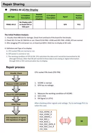
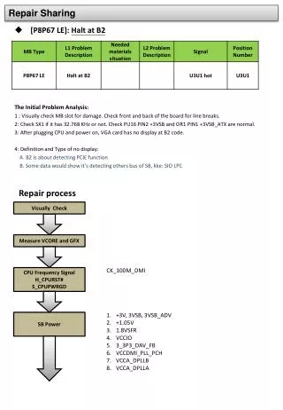
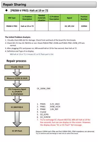
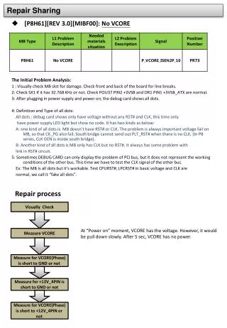
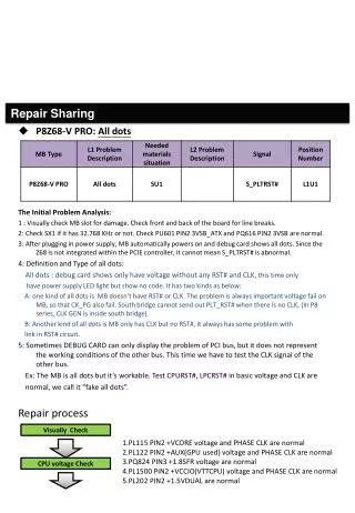
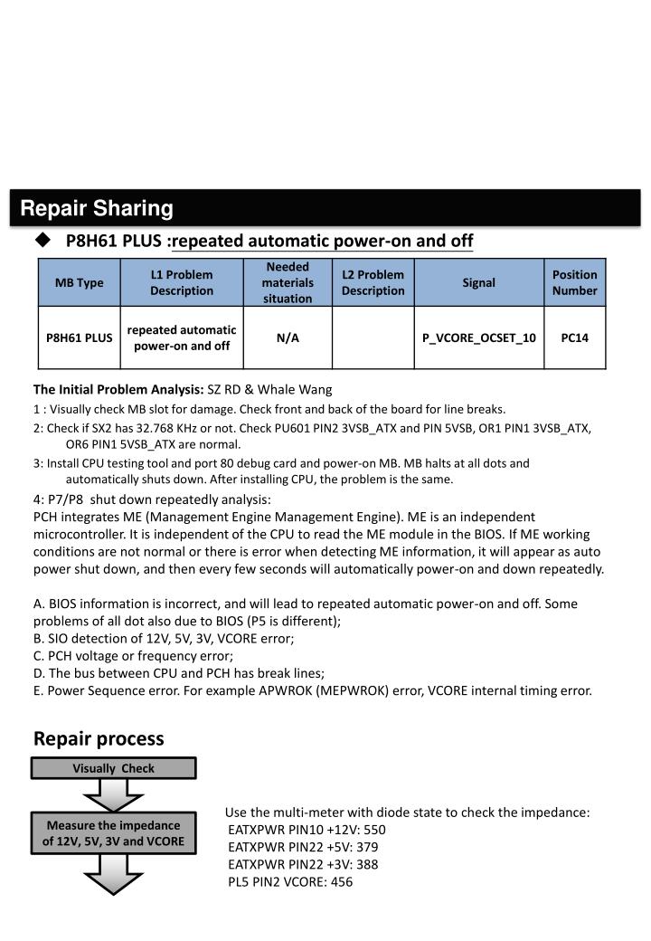
Repair Sharing • P8H61 PLUS :repeated automatic power-on and off • The Initial Problem Analysis: SZ RD & Whale Wang 1 : Visually check MB slot for damage. Check front and back of the board for line breaks. 2: Check if SX2 has 32.768 KHz or not. Check PU601 PIN2 3VSB_ATX and PIN 5VSB, OR1 PIN1 3VSB_ATX,OR6 PIN1 5VSB_ATX are normal. • 3: Install CPU testing tool and port 80 debug card and power-on MB. MB halts at all dots and automatically shuts down. After installing CPU, the problem is the same. • 4: P7/P8 shut down repeatedly analysis: • PCH integrates ME (Management Engine Management Engine). ME is an independent microcontroller. It is independent of the CPU to read the ME module in the BIOS. If ME working conditions are not normal or there is error when detecting ME information, it will appear as auto power shut down, and then every few seconds will automatically power-on and down repeatedly. • A. BIOS information is incorrect, and will lead to repeated automatic power-on and off. Some problems of all dot also due to BIOS (P5 is different);B. SIO detection of 12V, 5V, 3V, VCORE error; • C. PCH voltage or frequency error;D. The bus between CPU and PCH has break lines;E. Power Sequence error. For example APWROK (MEPWROK) error, VCORE internal timing error. • Repair process Visually Check Use the multi-meter with diode state to check the impedance: EATXPWR PIN10 +12V: 550 EATXPWR PIN22 +5V: 379 EATXPWR PIN22 +3V: 388 PL5 PIN2 VCORE: 456 Measure the impedance of 12V, 5V, 3V and VCORE 1
1. OR12 PIN1 O_12V_IN:1V 2. OR19 PIN1 O_5V_IN:1V 3. OU1C106 +3V:3V 4. OR5 PIN1 O_VCORE_IN:1.1V (Exclude “B” problem) 12VIN,5VIN,3V,VCORE_IN 1. +1.8VSFR PQ22 PIN3 2. +1.05PCH PQ21 PIN3 3. +1.05ME SR159 PIN2 4. +1.05V_PCH_SRC SR213 PIN2 5. VCC_XCKPLL SR208 PIN1 1.8V 6. VCC_XCKPLL_AFDI SR210 PIN1 1.8V 7. VCC_DPLLA SL4 PIN2 1.05V 8. VCC_DPLLB SL6 PIN2 1.05V 9. VCCDMI_PLL_PCH SR215 PIN2 0.67V(transfer in PCH) 10. VCCSATA_PLL_PCH SL8 PIN2 0.66V(transfer in PCH) 11. VCCUSB3_PLL_PCH SR212 PIN2 1.08V(transfer in PCH) The voltage of H61 chipset 1. SX3 25MHz,CX1 14MHz 2. CK_100M_DMIN,CK_100M_DMIP 3. CK_100M_EPCIN,CK_100M_EPCIP 4. CK_100M_LAN1N,CK_100M_LAN1P 5. CK_100M_PCHN,CK_100M_PCHP 6. CK_100M_PCIEX1_1N,CK_100M_PCIEX1_1P 7. CK_100M_PCIEX1_2N,CK_100M_PCIEX1_2P 8. CK_100M_PCIEX16_1N,CK_100M_PCIEX16_1P 9. CK_100M_SATAN,CK_100M_SATAP 10. CK_100M_USB3N,CK_100M_USB3P 11. CK_14M_PCH 12. CK_33M_EPCI 13. CK_33M_SIO 14. CK_48M_SIO 15. CK_96M_PCHN, CK_96M_PCHP (Exclude “C” problem) The frequency of H61 chipset 1. Use CPU testing tool to check DMI BUS. (If MB has integration graphics, FDI BUS needs to be checked) 2. Visually inspect CPU PIN and there are no break lines between CPU and PCH. (Exclude “D” problem) DMI 1. O_PWROK SR135 PIN1 3V 2. S_APWROK SR135 PIN2 3V 3. S_DPWROK SR183 PIN2 3V PWROK
The circuit of VCORE (ASP1000RM) 1. PU1 PIN41 VCC, PIN46 VRHOT, PIN44 TSENA, PIN34 ISENAN has 5V 2. PU1 PIN48 DVD, PIN47 DVDA 1.48V 3. PU1 PIN38 EN 1.05V 4. PU1 PIN9 RSET 1.1V 5. PU1 PIN11 FB 1.12V 6. PU1 PIN51~54 PWM1~4 are normal(Check the reference voltage , as chart1) Check VCORE with oscilloscope, it’s drop up before PLTRST. P_VCORE_VR_RDY_10 is drop before VCORE. Check ASP1000RM OCP, OVP, UVP part. P_VCORE_OCSET_10 voltage only has 280mV. (normal is 1.9V~2.1V). Try to remove PR38 and PR39, and check the impedance are normal. Remove PC14 and check the capacitor is abnormal. PC14 of two sides are short together. After exchange PC14, MB runs OK. (Chart 3) Remark: 1.ASP1000MR Power Sequence( Chart 4) P_VCORE_OCSET_10 Chart 1: Measure ASP1000RM voltage with CPU testing tool
Chart 2 Chart 3