Download
1 / 63
630 likes | 781 Views
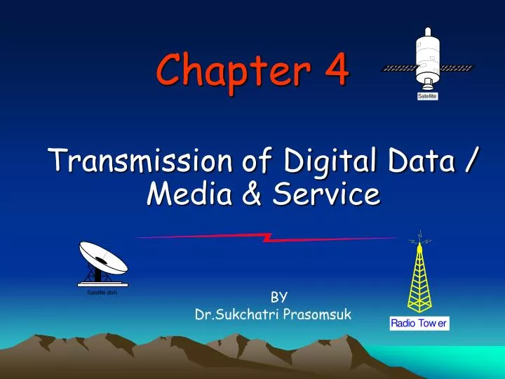
Chapter 4. Transmission of Digital Data / Media & Service. BY D r.Sukchatri Prasomsuk. Contents :. 4.1 Digital Data Transmission 4.2 DTE-DCE Interface 4.3 Modems 4.4 Type of Transmission Media. 4.1 Digital Data Transmission. Communication Mode :.

E N D
Chapter 4 Transmission of Digital Data / Media & Service BY Dr.Sukchatri Prasomsuk
Contents : • 4.1 Digital Data Transmission • 4.2 DTE-DCE Interface • 4.3 Modems • 4.4 Type of Transmission Media
4.1 Digital Data Transmission • Communication Mode :
4.1 Digital Data Transmission • Data Transmission Data Transmission Parallel Serial Synchronous Asynchronous
4.1 Digital Data Transmission • Parallel vs Serial line
4.1 Digital Data Transmission • Parallel Transmission : Transmission in which bits in a group are sent simultaneously, each using a separate link. 8 bits Sender ; Computer LPT1, LPT2, LPT3, etc. Receiver ; Printer, Plotter, Circuit, etc,
4.1 Digital Data Transmission • Serial Transmission : Transmission of data one bit at a time using only one single link. 8 bits are sent Sender (RS232) 0 1 0 1 0 1 0 1 0 1 0 1 0 1 0 1 Receiver (RS232) 0 1 0 1 0 1 0 1 Parallel/Serial Converter
4.1 Digital Data Transmission • Asynchronous Transmission : Transfer of data with start and stop bit(s) and a variable time interval between data units. • We send one start bit (0) at the beginning and one or more stop bits (1s) at the end of each byte. There may be a gap between each byte. • Asynchronous here means “asynchronous at the byte level” but the bits are still synchronized; their durations are the same.
4.1 Digital Data Transmission • Asynchronous Transmission : Clock independent Direction of flow Sender Stop bit Start bit Receiver Data 1101001110 1100011110 110011 Gaps
4.1 Digital Data Transmission • Asynchronous Transmission :
4.1 Digital Data Transmission • Synchronous Transmission : A transmission method that requires a constant timing relationship between the sender and the receiver. • We send bits one after another without start/stop bits or gaps. It is the responsibility of the receiver to group the bits.
4.1 Digital Data Transmission • Synchronous Transmission : Clock dependent Direction of flow Sender Receiver 10100111 10001111 11001101 Data
4.1 Digital Data Transmission • Bit Oriented synchronization :
4.1 Digital Data Transmission • Character Oriented synchronization : BiSync
4.2 DTE-DCE Interface • Data Terminal Equipment (DTE) : A device that is an information source or an information sink. It is connected to a network through a DCE. • Data Circuit-Terminal Equipment (DCE) : A device used as an interface between a DTE and a network.
4.2 DTE-DCE Interface • Data Terminal Equipment (DTE) : is any device that is a source of or destination for binary digital data. • Data Circuit-Terminal Equipment (DCE) : is any device that transmits or receives data in the from of an analog or digital signal through a network. • Interface : the electrical specification of EIA-232 defines that signals other than data must be sent using OFF -> lessthan -3 Volts and ON -> greater than +3 Volts
4.2 DTE-DCE Interface DTE DTE DCE DCE Interface; ~ 15 m. EIA-232, EIA-442, EIA-449 Interface EIA-232, EIA-442, EIA-449
4.2 DTE-DCE InterfaceSerial Implementation of DTE vs DCE Data Terminal Equipment End of the user’s device on the WAN link • Data Communications Equipment • End of the WAN provider’s side of the communication facility • DCE is responsible for clocking Modem CSU/DSU DCE DTE Internet DCE DTE DCE DTE
4.2 DTE-DCE InterfaceSerial Point-to-Point Connections End user device DTE CSU/DSU DCE Service Provider
4.2 DTE-DCE InterfaceFixed Interfaces Router—rear view Serial WAN ports can be fixed
4.2 DTE-DCE InterfaceModular Interfaces Serial WAN ports can be modular WAN Interface Card Router—rear view Module Ethernet 10BaseT Ethernet AUI ISDN BRI S/T Console
4.3 Modems • Modem stands for MOdulator/DEModulator. • Modem is a communication device that converts binary signal into analog acoustics signal for transmission over telephone lines and converts these acoustics signals back into binary form at the receiving end. • A Modulator converts a digital signal into an analog signal using ASK, FSK, PSK or QAM. (Digital-to-Analog) • A Demodulator converts an analog signal into a digital signal. (Analog-to-Digital)
4.3 Modems • Modem Type : • 1. Asynchronous : for Low speed communication • 2. Synchronous : for High speedcommunication • 3. Half-Duplex : must alternately send and received signals. • 4. Full-Duplex : can simultaneously handle two signals using two carriers to transmit and receive data.
4.3 Modems • Signal Constellation
4.3 Modems • Constellation Samples :
4.3 Modems • Some Standard : • V29 : -Transmission rate up to 9600 bps • V.32bis : -2-dimensional TCM with 128 points -Transmission rate up to 14,400 bps • V.32ter : -2-dimensional TCM with 512 points -Transmission rate up to 19,200 bps • V.34 : -2-dimensional TCM with 768 points -Transmission rate up to 28,800 bps
4.3 Modems • Error Correcting : • LAPD (Link Access Protocol D) : based on HDLC synchronous protocol. • MNP (Microcom Networking Protocol) : trademark of Microcom • TCM : modulation with error detecting code • V.42 : CRC error correcting standard
4.3 Modems • Fallback :
4.3 Modems • Intelligent Modems : contain software to support a number of additional functions, such automatic answering and dialing. • The AT command format is : AT command [parameter] command [parameter] command [parameter] ...
4.3 Modems • Hayes Commands set :
4.3 Modems • Hayes Response Code :
4.4 Type of Transmission Media • Transmission media can be divided into two broad categories: Transmission Media - Radio wave (Wireless) Guided UnGuided Twisted-pair cable Coaxial cable F/O cable Microwave Satellite Cellular
4.4 Type of Transmission Media • Twisted-pair cable: UTP (100 Hz - 5 MHz)
4.4 Type of Transmission Media • Twisted-pair cable : STP (100 Hz - 5 MHz)
4.4 Type of Transmission Media • UTP Category (CAT): • Category 1 : for telephone systems, low speed. • Category 2 : for voice and data transmission of up to 4 Mbps. • Category 3 : transmission of up to 10 Mbps. (Standard cable for telephone system) • Category 4 : transmission of up to 16 Mbps. Category 5 : transmission of up to 100 Mbps. • Category 6 : transmission of up to 250 Mbps.
Differentiating between Connections ISO 8877 (RJ-45) connectors and jacks are slightly larger than RJ-11 phone connectors and jacks AUI connectors are DB15 Fiber Connector Port
UTP Device Wire Pair T is Tip R is Ring Pin 1 Pair 2 T2 2 Pair 2 R2 1 3 Pair 3 T3 4 Pair 1 R1 5 Pair 1 T1 8 6 Pair 3 R3 7 Pair 4 T4 The RJ-45 Connector 8 Pair 4 R4
8 8 1 1 o UTP Implementation Straight-through Cable 10BaseT/100BaseT Straight-through Straight-through Cable 8 1 Hub/Switch Server/Router 8 1 Pin Label 1 TD+ 2 TD- 3 RD+ 4 NC 5 NC 6 RD- 7 NC 8 NC Pin Label 1 RD+ 2 RD- 3 TD+ 4 NC 5 NC 6 TD- 7 NC 8 NC Wires on cable ends are in same order
8 1 g o UTP Implementation Crossover Cable 10BaseT/100BaseT Crossover Crossover Cable Hub/Switch Hub/Switch 8 1 Pin Label 1 RD+ 2 RD- 3 TD+ 4 NC 5 NC 6 TD- 7 NC 8 NC Pin Label 1 RD+ 2 RD- 3 TD+ 4 NC 5 NC 6 TD- 7 NC 8 NC 1 8 8 1 br Some wires on cable ends are crossed
4.4 Type of Transmission Media • Coaxial Cable : (100 KHz - 500 MHz) • RG-8, RG-9, RG-11 used in thick Ethernet, Radio • RG-58 used in thick Ethernet, Radio Transmitter • RG-59 used for TV
4.4 Type of Transmission Media • Fiber Optic Cable : Typical
4.4 Type of Transmission Media • Fiber Optic Cable : Cable Structures
4.4 Type of Transmission Media • Fiber Optic Cable : Optical Comparison
4.4 Type of Transmission Media • Fiber Optic Cable : Light Source
4.4 Type of Transmission Media • Fiber Optic Cable : Transmission Mode
4.4 Type of Transmission Media • Telephone system :
4.4 Type of Transmission Media • Intra-Office cable :
Comparing Ethernet Media Requirements 100BaseTX 10Base5 10BaseT 100BaseFX 62.5/125 micron multi-modeF/O EIA/TIA Cat 3, 4, 5 UTP 2 pair EIA/TIA Cat 5 UTP 2 pair 50-ohm coax (thick) Media Maximum Segment Length 500 meters 100 meters 100 meters 400 meters Point-to-Point Topology Bus Star Star Duplex media- interface connector (MIC) ST ISO 8877 (RJ-45) ISO 8877 (RJ-45) Connector AUI
4.4 Type of Transmission Media • UnGuided Media : • Unguided media or wireless communication, transport electromagnetic waves without using a physical conductor. Instead, signals are broadcast through air. • VLF : Very low frequency (3KHz-30KHz)--Suface • LF : Low frequency (30KHz-300KHz)--Suface • MF : Middle frequency (300KHz-3MHz)--Tropospheric • HF : High frequency (3MHz-30MHz) --Ionospheric • VHF:Very high frequency (30MHz-300MHz)-Space & line of sight • UHF : Ultra high frequency (300MHz-3GHz) --Space • SHF : Super high frequency (3GHz-30GHz) --Space • EHF : Extremely high frequency (30GHz-300GHz) --Space