Download
1 / 13
130 likes | 292 Views
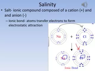
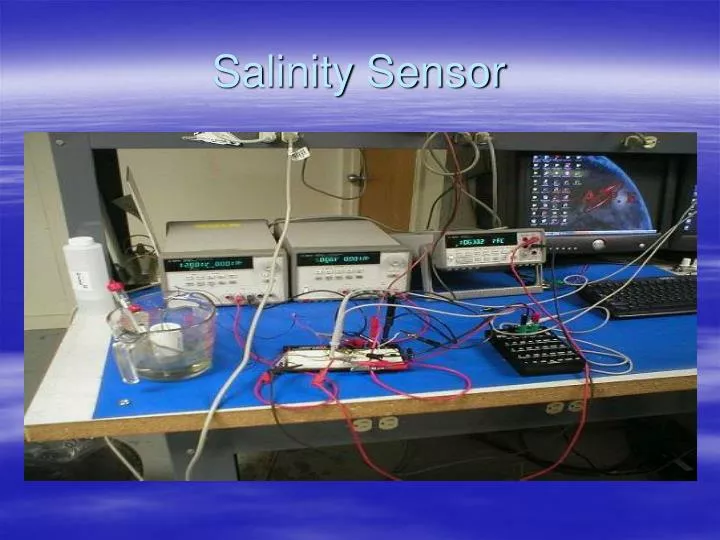
Salinity Sensor. Calibrated Solution and Electrode. - 50,000uS/cm from YSI Incorporated - Electrode apart - 1.3cm - 65000uS/1.3cm - Electrode Cross sectional Area (A) - 1.5mm^2 - Length of Electrode (L) - 1/5cm

E N D
Calibrated Solution and Electrode - 50,000uS/cm from YSI Incorporated - Electrode apart - 1.3cm - 65000uS/1.3cm - Electrode Cross sectional Area (A) - 1.5mm^2 - Length of Electrode (L) - 1/5cm - Resistivity (P) = (1/50000uS) *1.3cm = 20ohm *1.3cm = 26ohm*cm - Resistance = (P*L)/A - Estimated Resistance = 344963ohm
Electrode • NOTE: Epoxy would be put on electrode to make it about 1/3cm long.
WheatStone Bridge • Vin = Vabc = Vadc • Iabc(R3+Rx) = Iadc(R1+R2) • Vab = IabcR3 = Vin *R3 • R3+Rx • Vad = Iadc*R1 = Vin *R1 • R1+R2 • Vg = (V1 – V2) • Vg = Vab – Vad = VinR3 - VinR1 • R3+Rx R1 +R2 • Vg = ( R3 - R1 ) Vin • R3+Rx R1+R2 • Vg = Rx - R1 • Vin Rx+R3 R1+R2 • Vg + R1 = 1 • Vin R1 +R2 (1+ R3/Rx) • Rx = R3/ ( 1 -1 ) • (Vg/Vin + R1/(R1+R2))
Differential Amplifier • Vg = V1 – V2 • Vout = -Ra (Vg) • Rb • Vg = - (Vout*Rb) • Ra
Actual Vs Meausured Resistance • Actual • R1 = R2 = R3 = 4.3Kohms • Ra = Rb = 220kohms Measured - R 1 = 4.2560; R3 = 4.2827; R2 = 4.2967 - RA1 = 218.10K; RA2 = 220.50K; RB1 = 2204.8K RB2 = 217.05K
Calculation and Diagram • Set Vg of the bridge and amplifier to equal each other • Vout = -Ra( (RX/(RX+R3)) – (R1/(R1+R2))) • Rb
Test and Procedure 1. Connect the circuit • 2. Pour the 50,000uS/cm calibrated solution in the beaker up to 200ml (make sure the • temperature is about 25C to avoid worring about specific conductivity.) • 3. Record the DC output Voltage (V1 – V2) and solve for Rx (the electrode impedances) • 4. Pour the Solution out of the beaker until it reaches about 100ml in the beaker. • 5. Add some distilled water in the beaker to reach 200ml. (This basically reduces the • conductivity by half.) • 6. Measure the DC output voltage. • 7. Repeat procedure (4 – 6) until around measurements are made. • 8. Plot the Data: The concentration of Salt in the water, VS electrode impedances. • NOTE: PPM = (Electrical Conductivity(EC)) * 500.
Using Wheatstone Bridge Formula • Rx = R3/( 1 -1 ) • (Vg/Vin + R1/(R1+R2)) • Rx at Vg = 5.8814 • = 344963.4187 • Compared to Estimate It is similar