Download
1 / 16
160 likes | 252 Views
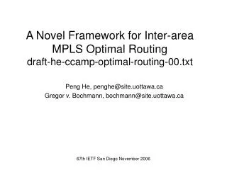
Architetture di routing BGP/MPLS. Alfio Lombardo. Architetture di routing in Internet. AS 2. IGP. AS 1. IGP. EGP. EGP. EGP. IGP. AS 3. BGP. iBGP. eBGP. eBGP. AS 3. IGP. IGP. IGP. AS 2. AS 1. 195.31.235.88. 195.31.235.88. 195.31.235.88. Limiti architettura del routing BGP.

E N D
Architetture di routingBGP/MPLS Alfio Lombardo
Architetture di routing in Internet AS 2 IGP AS 1 IGP EGP EGP EGP IGP AS 3
BGP iBGP eBGP eBGP AS 3 IGP IGP IGP AS 2 AS 1
195.31.235.88 195.31.235.88 195.31.235.88 Limiti architettura del routing BGP Tutti i router (interni e di bordo) di un AS di transito devono mantenere nelle loro tabelle tutte le destinazioni esterne annunciate dai BGP ESEMPIO: 195.31.235.0/24 R[2] non conosce la destinazione 195.31.235.0/24 AS Y R[2] Annuncio BGP Rete: 195.31.235.0/24 R[1] R[3] AS X Annuncio IGP Rete: 195.31.235.0/24 Annuncio IGP Rete: 195.31.235.0/24
Architetture di routing BGP/MPLS iBGP eBGP LSP MPLS AS Y AS X Cliente AS X LSR interni dell’AS X Cliente AS Y • Nei router interni permangono solo le informazioni necessarie a raggiungere • i router di bordo: • Non e’ piu’ necessario redistribuire le informazioni esterne su IGP • Si risparmia memoria
Sessione iBGP: Annuncio di X +Label L1 Sessione eBGP IGP+LDP IGP+LDP IGP+LDP RE2 distribuisce a RE1 l’associazione L1 / X via LDP o iBGP L4 L1 L1 L1 L3 L2 IGP routing RE2 RI1 BGP routing X RE21 RI12 distribuisce a RE1 l’associazione L2 / RE2 via LDP AS di transito: ingresso pacchetto non etichettato AS 3 RE[1] RE[2] RI[1] RI[2] AS 2 RC[1] X LSR interni dell’AS AS 1 Pacchetto non etichettato destinato a X BGP routing X RE2 IGP routing RE2 RI2
Annuncio eBGP Rete = 195.31.235.0/24 BGP Next-Hop = Milano MIX-3 Etichetta = 54 Annuncio iBGP Rete = 195.31.235.0/24 BGP Next-Hop = Milano MIX-2 Etichetta = 64 64 74 54 64 64 36 35 AS di transito: ingresso pacchetto etichettato (swap 74 – 64) AS 3 ASBR Roma ASBR Milano MIX-2 ASBR Milano MIX-3 IGP+LDP IGP+LDP IGP+LDP LSR Roma LSR Milano AS 2 Pacchetto etichettato FEC = 195.31.235.0/24 195.31.235.0/24
AS singolo: visione logica Attenzione N(N-1)/2 sessioni i-BGP Sito Cliente Sito Cliente Sito Cliente RIP, OSPF, E-BGP, Statico i_BGP Sito Cliente Sessioni iBGP tra Edge-LSR (due) LSP (monodirezionali) tra Edge-LSR
Annuncio IGP Rete = 195.31.235.0/24 Next-Hop = CE-X Pacchetto IP Dest. = 195.31.235.88 Annuncio iBGP Rete = 195.31.235.0/24 BGP Next-Hop = Edge-LSR Roma 45 35 AS singolo: esempio 195.31.235.0/24 Edge-LSR Milano Edge-LSR Roma CE-X LSR Milano LSR Roma IGP+LDP IGP+LDP IGP+LDP Sito Cliente
Route reflector Verso altri Route Reflector CLUSTER Route Reflector RR RR-C RR-C RR-C RR-C Route Reflector Client Sessione BGP
Annuncio riflesso ad altri RR CLUSTER RR Annuncio riflesso Annuncio BGP Annuncio riflesso Annuncio riflesso RR-C RR-C RR-C RR-C
Architettura Route Reflector fault tolerant Verso altri Route Reflector CLUSTER RR-1 RR-2 RR-C RR-C RR-C RR-C
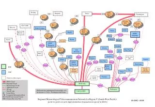
. . . . . . RR di 1^ livello RR-1 RR-2 RR di 2^ livello RR-2 RR-2 POP X RR-1 RR-1 RR-2 RR-2 . . . . . . RR-2 RR-2 RR-1 RR-1 POP Y POP Z
TTL IP =125 TTL MPLS =124 TTL MPLS =99 TTL IP =98 TTL IP =97 Pacch. IP Pacch. IP Pacch. IP L’Edge-LSR prima decrementa il valore di “TTL IP” e quindi copia il TTL risultante sull’elemento più esterno della pila MPLS L’ LSR che a seguito di una operazione di “pop” elimina un elemento della pila MPLS, decrementa il TTL e lo copia nel campo TTL dell’elemento successivo dell’intestazione MPLS, o, qualora non vi siano più elementi, nel campo TTL dell’intestazione IP Pacch. IP Pacch. IP Ln L1 Gestione TTL
# 3: Traceroute 195.35.10.10 TTL = 2; Porta UDP = 45678 # 4: Traceroute 195.35.10.10 TTL = 1; Porta UDP = 45678 # 1: Traceroute 195.35.10.10 TTL = 1; Porta UDP = 45678 # 2: ICMP “Time Exceeded” # 5: ICMP “Port Unreachable” # 6: ICMP “Port Unreachable” Traceroute Nelle reti IP…….
MPLS TTL =1 ICMP ICMP IP L1 L2 Pacchetto ICMP generato da L[b] Pacchetto proveniente dal sito sorgente dell’applicazione “traceroute” Traceroute Nelle reti BGP/MPLS……. EL[d] EL[a] L[c] L[b] Route di default Metodo: default route