Download
1 / 47
490 likes | 736 Views
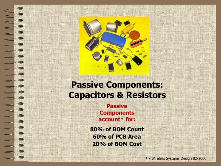
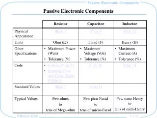
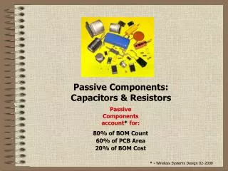
Passive Components: Capacitors & Resistors . Passive Components account * for: 80% of BOM Count 60% of PCB Area 20% of BOM Cost. * - Wireless Systems Design 02-2000. Topics: General Thru-Hole & SMT Assembly … pages 3 ~ 6 Products Capacitors … pages 7 ~ 36

E N D
Passive Components: Capacitors & Resistors Passive Components account* for: 80% of BOM Count 60% of PCB Area 20% of BOM Cost * - Wireless Systems Design 02-2000
Topics: General Thru-Hole & SMT Assembly …pages 3 ~ 6 Products Capacitors …pages 7 ~ 36 Resistors …pages 37 ~ 47 • Types – Markets – Characteristics • Substitution Guidelines • Appearance – Sizes – Marking 2
Thru-Hole Assembly • . Leaded parts are inserted into holes in circuit board • . Leads are clinched and cut. • . Molten wave of solder connects leads to board. Wave of molten solder Direction of Assembly Flow 3
Surface Mount (SMT) Assembly • . Solder paste is printed onto land patterns. 4 PCB
Surface Mount (SMT) Assembly 2. SMT parts are placed (by automatic pick and place equipment) onto solder paste covered land patterns. Vacuum Nozzle 5
Surface Mount (SMT) Assembly 3. Circuit board is run through a reflow soldering oven. Where the solder paste liquefies, and electrically connects the SMT component terminations to the circuit board land patterns. As the circuit board moves out of heating zone the liquid solder solidifies mechanically fixing the SMT components to the circuit board. 6
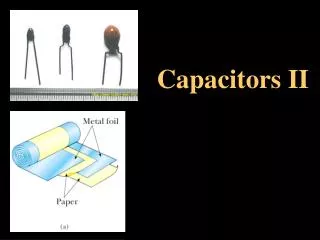
Capacitor Family Tree CAPACITORS ELECTROSTATIC ELECTROLYTIC CERAMIC FILM ALUMINUM TANTALUM • Non polarized • AC or DC operation • Lower Capacitance • Polarized • DC operation • Higher Capacitance 7
Markets CAPACITORS ELECTROSTATIC ELECTROLYTIC CERAMIC FILM ALUMINUM TANTALUM • Biggest market • Lowest Cost • 1206 Long LT • 0603 & 0402 good choices • Large Cap at low cost • SMT increasing LT • Price flat on TH • Large Cap in Small Sizes • Long LT • Price Increases on C/ D/ E sizes • Better performance at higher cost • SMT longer LT 8
Capacitance Values CERAMIC CERAMIC FILM FILM TANTALUM ALUMINUM 1.0pF 0.10uF 10uF 1000uF F = micro-Farad = 1 x 10⁻⁶ F = 1 millionth of a Farad nF = Nano-Farad = 1 x 10⁻⁹ F = 1 billionth of a Farad pF = Pico-Farad = 1 x 10-12 F = 1 trillionth of a Farad ALUMINUM TANTALUM CERAMIC FILM 9
Capacitance Values – EIA Codes 3 digit code (pF) 3 digit code “R” represents decimal point 4R7 = 4.7pF TANTALUM CERAMIC FILM 3 digit code First 2 digits are significant. Third digit is number of zeros. 101 = 100pF 10
Capacitance Values – EIA Codes 3 digit code (pF) 103 = 10,000pF 103 = 10nF 103 = 0.01uF TANTALUM CERAMIC FILM 104 = 100,000pF 104 = 100nF 104 = 0.1uF 106 = 10,000,000pF 104 = 10,000nF 104 = 10uF 11
Capacitance Values – EIA Codes 3 digit code (uF) 3 digit code “R” represents decimal point R33 = 0.33uF ALUMINUM 3 digit code First 2 digits are significant. Third digit is number of zeros 471 = 470uF 12
Capacitance Values • Standard Capacitance Values: • Electrolytic Capacitors: Aluminum & Tantalum • 10 22 33 47 • Examples: • 0.1, 0.22, 0.33, 0.47… 1.0, 2.2, 3.3, 4.7. 10, 22, 33, 47… • 100, 220, 330 … 13
Capacitance Values • Standard Capacitance Values: (PER EIA-575 & RS 460) • Electrostatics: Ceramic & Film • E12: 10 12 15 18 22 27 33 39 47 56 68 82 • Examples: • 1.0, 1.2, 1.5,…. 10, 15, 22,… 100, 180, 270,… 1K, 3.3K, 4.7K,… • 10K, 33K, 56K,… 560K, 680K, 820K,… 1uF, 2.2uF, 4.7uF,… 14
Capacitance Values • Standard Capacitance Values: (PER EIA-575 & RS 460) • Electrostatics: Ceramic & Film • E24:10 11 12 13 15 16 18 20 22 24 27 30 33 36 39 43 47 51 56 62 68 75 82 91 In-between Values Shown In Red Are Considered “Odd” Non-Preferred Values And As Such Are Not Stocked And Should Be Discouraged From Being Selected 15
Component Characteristics Substitution Guide: Capacitors » Capacitance Value Substitution In many cases increasing to higher capacitance value is acceptable i.e… 2200uF part can be considered for use in place of 1500uF part i.e… 3.3uF part can be considered for use in place of 2.2uF part i.e… 0.22uF part can be considered for use in place of 0.1uF part 16
Tolerance Capacitance Tolerance : The allowable window - limits that the capacitors’ +25°C (room temperature) capacitance value will be within. 1 digit code ALUMINUM CERAMIC CERAMIC CERAMIC FILM TANTALUM CERAMIC CERAMIC FILM 17
Component Characteristics Substitution Guide: Capacitors » Capacitance Tolerance Substitution “A component with a tighter (better) tolerance can replace a looser (worst) tolerance component.” i.e... ±1%(F) tolerance part can replace ±2%(G), ±5%(J) or ±10% (K) tolerance part i.e... ±2%(G) tolerance part can replace ±5%(J), ±10% (K) or ±20% (M) tolerance part i.e... ±5%(J) tolerance part can replace ± 10%(K) or ±20% (M) tolerance part i.e… ±10%(K) tolerance part can replace ±20%(M) or +80%/-20%(Z) tolerance part i.e… ±20%(M) tolerance part can replace +80%/-20%(Z) tolerance part 18
Voltage Rating Voltage Rating The maximum VDC that can be applied to the capacitor Range of Voltage Ratings: 2.0VDC ~ 15,000VDC 2 digit code 19
Component Characteristics Substitution Guide: Capacitors » Capacitance Voltage Rating Substitution “A component with a higher voltage rating may be used in place of, or as a substitute for, a lower voltage rated component.” i.e… 1000V rated part can replace 500V, 250V or 100V rated part. i.e… 500V rated part can replace 250V , 100V or 50V rated part. i.e… 250V rated part can replace 100V, 50V or 25V rated part. i.e… 100V rated part can replace 50V or 25V rated part. i.e… 50V rated part can replace 25V or 16V rated part. i.e… 25V rated part can replace 16V or 10V rated part. 20
TC Characteristic Each Capacitor will have a temperature coefficient (TC). TC is a measure of how the capacitance value behaves over temperature. All parts are supplied to be within tolerance at room temperature(+25°C = +77°F) Aluminum Electrolytic styles have TC of±20% over -40°C to +105°C Tantalum Electrolytic styles have TC of ±5% over -55°C to +85°C Filmstyles have TC of ±7% over -40°C to +105°C +10% 000 -10% -20% -30% -50C +25C +100C 21
TC Characteristic Unfortunately not all capacitance values can be produced from one ceramic dielectric formulation… A wide range of ceramic dielectrics are needed, and have been developed, to cover a broad range of capacitance values. The EIA (Electronics Industries Alliance) established industry classifications for ceramic dielectrics that are agreed to and met by all ceramic capacitor producers. These ceramic dielectric classifications are identified by their temperature coefficient (TC) code. Y5F Y5P X7R Z5U NPO 22
TC Characteristic Standard Temperature Coefficients (TC) of ceramic capacitors: X7R= ±15% C over -55°C ~ + 125°C 23
Component Characteristics Substitution Guide: Capacitors » Temperature Coefficient Substitution “A component with a more stable (better) temperature characteristic (TC) can replace a less temperature stable (worse) component. i.e…an X7R ceramic can replace Z5U or Y5V ceramic parts. i.e…an NPO ceramic can replace a X7R or Z5U or Y5V ceramic. NPO… X7R… X5F… X5P… X5R… XRS… X5T… Y5U… Y5V… Z5U… Z5V... MOST STABLE LEAST STABLE 24
Capacitance Range per TC Multilayer Ceramic Chip Capacitor Temperature Coefficients: NPO X7R Y5V Z5U 25 0.5pF 1pF 10pF 100pF 1nF 10nF 100nF 1uF 10uF
Radial Leaded Electrolytic Capacitors Appearance • Cathode lead (-) shorter than anode (+) • Cathode polarity band or anode strip • Date code (YYWW) “9614” = 14th week of 1996 • Temperature rating • Capacitance value (µF) • Voltage rating (VDC) • Logo 26
Axial & Snap-In Leaded Electrolytic Capacitors Appearance • Cathode polarity band • Date code (YYWW) “9614” = 14th week of 1996 • Temperature rating • Capacitance value (µF) • Voltage rating (VDC) • Logo 27
Film Capacitor (Radial Leaded) • Capacitance value (pF) & Tolerance Code • Voltage rating (VDC) 29
SMT Electrolytic Capacitors Appearance • Cathode (-) & Anode (+) markers • Capacitance value (µF) • Voltage rating (VDC) • Date Code 30
Dimensions (Surface Mount) English Metric Length Width 0402 1005 1.0mm (0.04”) 0.5mm (0.02”) 0603 1608 1.6mm(0.06”) 0.8mm (0.03”) 0805 2012 2.0mm (0.08”) 1.2mm (0.05”) 1206 3216 3.2mm (0.12”) 1.6mm (0.06”) 1210 3225 3.2mm (0.12”) 2.5mm (0.10”) 1812 4532 4.5mm (0.18”) 3.2mm (0.12”) 2225 5764 5.7mm (0.22”) 6.4mm (0.25”) No Component Marking WIDTH LENGTH 31
Surface Mount Tantalum Electrolytic Capacitors Case Code Metric English Length Width P 2012 0805 2.0mm (0.08”) 1.2mm (0.05”) A, A2 3216 1206 3.2mm (0.12”) 1.6mm (0.06”) B, B2 3528 1411 3.5mm (0.14”)2.8mm (0.11”) C 6032 2412 6.0mm (0.24”)3.2mm(0.12”) D1* 5846 2318 5.8mm (0.23”) 4.6mm(0.18”) D, E 7343 2917 7.3mm (0.29”) 4.3mm (0.17”) * - D1is Japanese size 32
Surface Mount Film Chip Capacitors English Metric Length Width 0805 2012 2.0mm (0.08”) 1.2mm (0.05”) 1206 3216 3.2mm (0.12”) 1.6mm (0.06”) 1210 3225 3.2mm (0.12”) 2.5mm (0.10”) 1913 4833 4.8mm (0.19”) 3.3mm (0.13”) 2416 6041 6.0mm (0.24”) 4.1mm (0.16”) 33 No Component Marking
Reel Labeling Part Number, Product Lot Number and Date Code identified on product reel labels provides trace-ability to production 34
Resistor Family Tree RESISTORS LEADED SMT CARBON FILM +/-5% GENERAL PURPOSE THICK FILM METAL FILM THIN FILM +/-1% HIGHER PERFORMANCE METAL OXIDE FILM +/-1% +/-5% GENERAL PURPOSE WIREWOUND <+/-1% SPECIAL HIGH POWER >2W HIGH POWER 37
Resistor Family Tree RESISTORS LEADED SMT • Higher cost • Lower volumes • Performance applic driven CARBON FILM THICK FILM METAL FILM THIN FILM METAL OXIDE FILM • Lowest cost • Largest Qty’s • Increasing LT & Pricing for larger sizes (>0805) • Mature Market • Flat Pricing • Declining Qty’s WIREWOUND 38
Resistor Characteristics RESISTANCE VALUE Resistance is expressed inohms(). Typical resistance values are industry standard (E24 & E96) values from 1.0 ohm to 10 Meg-ohms (10,000,000 ohm = 10MegOhm) 39
Leaded Types • Axial Leaded Styles Carbon Film Metal Film Metal Oxide 44
Leaded Types • Single In-Line Package (“SIP”) • in 4 pin to 13 pin package Isolated 1 2 3 4 5 6 7 Common / Bussed 45
SMT Types English Metric Length Width 0201 0502 0.5mm (0.02”) 0.25mm (0.01”) 0402 1005 1.0mm (0.04”) 0.5mm (0.02”) 0603 1608 1.6mm(0.06”) 0.8mm (0.03”) 0805 2012 2.0mm (0.08”) 1.2mm (0.05”) 1206 3216 3.2mm (0.12”) 1.6mm (0.06”) 1210 3225 3.2mm (0.12”) 2.5mm (0.10”) 1812 4532 4.5mm (0.18”) 3.2mm (0.12”) 2225 5764 5.7mm (0.22”) 6.4mm (0.25”) Thick Film Chips 46
SMT Types Thick Film Arrays 47


![G6 - CIRCUIT COMPONENTS [3 exam question - 3 groups]](https://cdn2.slideserve.com/4345025/g6-circuit-components-3-exam-question-3-groups-dt.jpg)